Initial concept
The analysis of the world market for spacecraft launching services shows that there are now great demands for launching spacecraft into geostationary orbit (the orbital plane coincides with the equatorial plane, the height above the Earth's surface is 35,800 km). It is assumed that this situation will continue in the future. However, the launch vehicles used have limited capabilities, do not satisfy potential customers either because of the cost or because of the quality of the services provided.
One of the ways to increase the efficiency of launch vehicles that deliver satellites into geostationary orbit and, accordingly, to reduce the cost of such delivery, is to launch launches from the equatorial zone. This is explained by the fact that with such launches, for example, from the Baikonur cosmodrome located at a latitude of 46 degrees, it is necessary to carry out special orbital maneuvers with high energy costs to turn the launch plane into the equatorial plane. In addition, the further from the equator the cosmodrome is located, the less the effect of the Earth's rotation is used. As a result, the Zenit launch vehicle, when launched from the near-equatorial region, can put a spacecraft with a mass twice as large as if it was launched from Baikonur into a geostationary orbit.
The construction of a cosmodrome on the territory of countries located in the equatorial region is very problematic for Russia, and its operation would require the costs of alienating the land both for the construction of launch and technical complexes with the necessary safety zone, and for the areas where detachable stages of launch vehicles and fairing flaps fall. spacecraft. It should also be taken into account that the number of launch routes is significantly limited by the location of densely populated areas. The maintenance of cosmodromes located in uninhabited areas requires the creation and maintenance of an appropriate ramified infrastructure. That is why the idea arose to create a floating rocket and space complex.
One of critical factors, which was taken into account in the formation of the concept of the Sea Launch complex, is the great experience of Russian and Ukrainian enterprises in the development, production and operation of modern relatively inexpensive launch vehicles and launch rocket complexes and the fact that the manufacture of about 80% of commercial spacecraft is concentrated in the United States. The adopted concept of creating a new competitive rocket and space complex includes the following main provisions:
- the use of modern launch vehicles, production technologies, components of missile systems and flight control facilities developed in Russia and Ukraine;
- autonomy of the launch and technical complexes providing preparation and launch of the launch vehicle using mobile marine vehicles;
- carrying out launches from ocean waters, including from near-equatorial areas;
- preparation of spacecraft for launch on the territory of the United States, located not far from the main manufacturers of commercial spacecraft, creation of comfortable working conditions for customers;
- a guarantee of the shortest terms of the complex creation, the project payback due to the provision of spacecraft launch services for no more than 5 - 7 years.
Main characteristics
The mass of the spacecraft to be withdrawn (including the mass of the transitional structural elements between the upper stage or the launch vehicle and the spacecraft) is:
- to geostationary orbit - up to 2.9 t;
- to the geotransfer orbit - up to 6.0 t;
- to low near-earth orbits with an inclination of 0-90 deg. - 11-15 t.
The number of launches per year is up to 8.
The time before the launch from the moment of signing the contract with the customer of the spacecraft is no more than 18 months.
The probability of failure-free operation of launch vehicles is not less than 0.95.
Coordinates of the main launch area - 0 deg. sh., 152 degrees h.d.
Components of the complex.
Rocket and space complex "Sea Launch" can be conventionally represented as consisting of three segments - rocket, spacecraft and sea.
The rocket segment includes:
- Zenit-2S launch vehicle and DM-SL upper stage;
- complexes of technological equipment and systems for preparation and launch of a space rocket;
- complex of automated control systems for preparation and launch;
— automated system flight control of the upper stage with attracted funds;
- measuring complex;
- coastal complex.
The spacecraft segment consists of a payload block with spacecraft and a base port. The offshore segment includes a launch platform and an assembly and command vessel.
Launch vehicle "Zenit-2S". The Zenit two-stage launch vehicle (lead developer - Yuzhnoye Design Bureau named after MK Yangel, manufacturer - PO Yuzhmashzavod, Dnepropetrovsk) and its ground complex serve as the basis for the Sea Launch project. Since 1985, 26 launches of these LVs have been carried out from the Baikonur cosmodrome. Zenit (Fig. 1) is a modern launch vehicle, which is distinguished by its ease of operation and full automation of the preparation and launch process. Taking into account the peculiarities of the sea launch, individual systems and sections of the launch vehicle are being modified or finalized, as a result of which it received the designation Zenit-2S.
Upper stage DM-SL. The DM Upper Stage (the lead designer and manufacturer of SP Korolev RSC Energia) is widely used in conjunction with the Proton launch vehicle to launch spacecraft into high-energy orbits, including geostationary ones. The block (Fig. 2) for carrying out orbital maneuvers has the ability to repeatedly turn on the propulsion engine and is characterized by high proven reliability. With the aim of adapting to the Zenit launch vehicle, as well as taking into account the peculiarities of the sea launch, individual systems and sections of the upper stage are modified or finalized. In this regard, the block received the index DM-SL.
Payload block. The payload unit is being developed by the Boeing Commercial Space Company and is intended to be installed in spacecraft. The block will be manufactured taking into account the application the latest technologies and includes a carbon fiber fairing, transitional structural elements between spacecraft and the upper stage DM-SL, electrical systems, a thermostatting system. Its diameter is 4.15 m, the length with the launch of one spacecraft is 11.39 m, with the launch of two - 16 m.
Launch platform. To support launches of a space rocket, Kvarner is modifying an offshore platform that it created for oil production. The platform is self-propelled, semi-submersible, of the catamaran type (Fig. 3). Main characteristics: displacement (on the move) - 27,300 tons, speed - up to 12 knots, length - 133 m; width - 75 m; height (to the main deck) - 42 m.
The platform, which is a floating launch vehicle, is equipped with a launch pad, a launch vehicle installer, fueling systems and other systems that provide preparation and launch of a space rocket. The platform is equipped with rocket segment systems and equipment at a Russian shipyard.
 Assembly and command ship. When creating an assembly and command vessel, the structure of a cargo ship of the Ro-Ro type (roll-on, roll-off) was used. The head developer and manufacturer is Kvarner. Main characteristics: displacement - 30,800 tons, speed - up to 16 knots, length - 200 m, width - 32 m.
The assembly and command ship performs the functions of: a technical complex (complex tests of the launch vehicle and the upper stage, assembly of a space rocket); filling station (filling the upper stage with high-boiling fuel components and gases); control center for the preparation and launch of a space rocket, flight control of the upper stage; center for receiving and processing measurements. The vessel is equipped with rocket segment systems and equipment at a Russian shipyard.
The assembly and command ship accommodates up to 240 people of the crew and personnel involved in the preparation and conduct of the launch, including representatives of the customer, living conditions are created close to those on cruise ships (there are one - double cabins, conference rooms, theater, living rooms, cafeterias, rooms for games, gym, swimming pool).
Coastal complex. The onshore complex is being built on the basis of the Primorsky branch of RSC Energia and will have to provide reception, storage and loading (at the port of departure) onto the carrier vessel of the stages of the Zenit-2S launch vehicle and upper stages, as well as fuel components produced in Russia ...
Base port. The base port is located in Long Beach (Los Angeles area, USA). Its purpose is to ensure the preparation of spacecraft, mooring of the launch platform and the assembly and command vessel, refueling of propellants and gases, loading the stages of the launch vehicle, upper stage and payload block onto the assembly and command ship.
Basic operations.
The manufactured stages of the Zenit-2S launch vehicle and upper stages (2-3 sets and fuel for the launch vehicle (kerosene) produced in Russia are delivered to the port of departure, loaded onto a chartered carrier ship and transported to the base port. Transit time is about one month ...
At the base port, the spacecraft is checked in a special structure, fueled with propellants and gases, and installed in the payload unit. Then the systems and equipment located on the launch platform and the assembly and command vessel are prepared for preparatory and pre-launch work, tanks and cylinders are filled with the appropriate propellants and gases. The stages of the launch vehicle, the upper stage, the payload block with the spacecraft are delivered to the assembly and command ship. Complex tests of the booster and the booster block are carried out there, the booster block is refueled with high-boiling propellants and gases, the booster block and the payload block are docked with the booster rocket. The assembled space rocket (designated "Zenith-3SL") is reloaded from the assembly and command ship to the hangar on the launch platform.
The launch platform with the Zenit-3SL LV and the assembly-command vessel are transferred to the designated area of the ocean for launching.
If the start is assigned from the main area at the equator (152 deg.W), the transition time to it is 11 days.
In the launch area, the launch platform is brought to a semi-submerged state, the launch vehicle is removed from the hangar by the installer and installed on the launch pad. The systems located on the launch platform and the assembly and command vessel are being prepared for pre-launch and launch operations, control checks of the launch vehicle, the upper stage and the spacecraft are carried out. All personnel and crew from the launch platform are evacuated to an assembly and command vessel located five kilometers from the launch site, and further control and management is carried out by radio communication. Refueling of the launch vehicle and the upper stage and launching of the LV occurs in an automatic mode.
To ensure the transfer of measurement results and flight control at the launch site, the Russian vessel (floating measuring station) Selena-M, the Mission Control Center near Moscow, ground measuring stations in Russia and Kazakhstan will be involved.
The main participants in the project.
The creation of the Sea Launch complex and its operation are envisaged to be carried out on a commercial basis, without attracting financial state funds, but certainly under the control and with the support of state institutions. These are, first of all, the Russian Space Agency and the Ministry of Defense Industry, the National Space Agency of Ukraine, the US Department of Commercial Space Transport.
A joint venture Sea Launch (Sea Launch) is already working on the project, the founders of which are the American aircraft and space company Boeing, the Russian Rocket and Space Corporation Energia named after V. SP Koroleva, the largest shipbuilding company in Europe - the Norwegian company "Kvarner", the leading aerospace enterprises of Ukraine PA "Yuzhmashzavod" and KB "Yuzhnoye" named after M.K. Yangel.
Boeing is responsible for the creation of the payload unit and the base port, and ensures interaction with customers and spacecraft developers. RSC Energia, Design Bureau Yuzhnoye and the enterprises involved in Russia and Ukraine ensure the manufacture of the rocket segment, the Kvarner company modifies the launch platform, builds an assembly and command vessel. Firms Boeing and Kvarner act not only as participants, but also as investors in the project. The implementation of the innovative project will be supported by the World Bank, the International Bank for Reconstruction and Development, and a number of major commercial banks.
The first launch is planned for 1998. The authority and experience of the participants in the Sea Launch project, the originality of the concept, as well as the widespread use of already well-proven, proven structures of rocket and space technology and shipbuilding are the key to success.
26th December 1996 14:52. Category Views: 1324-- [ Page 1 ] --
Fdorov Alexey Vladimirovich
BASICS OF ROCKET-SPACE DEVICE
COMPLEXES
Tutorial
INTRODUCTION ................................................. .................................................. ................ 5
SECTION 1. FUNDAMENTALS OF CONSTRUCTION OF ROCKET AND SPACE
COMPLEXES ................................................. ................................................. 7 BASIC INFORMATION ABOUT SPACE SYSTEMS.
1 STRUCTURE OF THE SPACE SYSTEM AND THE SPACE COMPLEX ........................................... .................................................. ........ 7 1.1 Structure of the space system ..................................... ................................ 7 1.2 Space communication systems ............. .................................................. ............. 1.3 Space navigation systems ................................. ......................... 1.4 Space meteorological systems ..................... ............................... 1.5 Space missile attack warning systems ............ ..... 1.6 Space observation systems ......................................... ....................... PURPOSE AND COMPOSITION OF THE ROCKET-SPACE COMPLEX .................... .................................................. ............................. 2.1 Space complex: purpose and composition of the main parts ............ ..... 2.2 Rocket and space complex: composition and purpose of the main elements SECTION 2. BASICS OF THE DEVICE OF ROCKETS-ROCKETS, RUNNERS AND SPACE VEHICLES ............................... ............... REMOVAL MEANS ................................. ............................................ 3.1 General information about launch vehicles .............................................. .............. 3.2 Engines for launch vehicles ............................... .............................................. 3.3 Conditions for the operation of the rocket -carrier ............................................. 3.4 Case design launch vehicle ............................................... .......... 3.5 Onboard systems of the launch vehicle ............................
.................................. 3.5.1 Executive bodies control systems of the launch vehicle ............. 3.5.2 Separation systems of the launch vehicle ........................ ................................ 3.5.3 Pneumohydraulic systems of the launch vehicle .......... .......................... 3.6 Upper stages ..................... .................................................. ........................ SPACE VEHICLES ........................ .............................................. 4.1 General information about spacecraft. Tendencies of changes in the design of modern spacecraft ..................................... 4.2 Principles of construction of structural and layout diagrams and the device of spacecraft .............................................. .................................... 4.3 Operating conditions of spacecraft spacecraft ........ ................. 4.3.1 Loading of spacecraft ........................... ............................... 4.3.2 Sparseness of the medium (space vacuum) .......... ................................... 4.3.3 Meteor showers and space debris ....... ............................................ 4.3.4 Weightlessness .. .................................................. ............................................... 4.3.5 Space radiation (radiation) and heat fluxes ............................ TECHNICAL BASIS OF ROCKET AND SPACE TECHNOLOGY .. 5.1 Structural materials of rocket and space technology .................. 5.2 Heat-shielding materials ....... .................................................. .................. SECTION 3. FUNDAMENTALS OF PROCESSING EQUIPMENT OF ROCKET AND SPACE COMPLEXES ........ GENERAL INFORMATION ABOUT PROCESSING EQUIPMENT OF ROCKET AND SPACE COMPLEX .... ...................................... 6.1 Basic information about cosmodromes ....... .................................................. .... 6.2 Basic information about the positional area of the rocket and space complex .................................... .................................................. .................. 6.3 General information on technological equipment of rocket and space complexes ...................... .................................................. .............................. 6.4 The concept of a generalized technological process. Content and sequence of technological operations from ILV to TC and SC ........ 6.4.1 Content of the main work carried out with rocket and space technology at the technical complex ... ............................................. 6.4.2 Contents of the main work carried out with rocket and space technology at the launch complex ....................................... ...................... PURPOSE AND COMPOSITION OF TECHNOLOGICAL EQUIPMENT OF TECHNICAL AND STARTING COMPLEXES ................... .......... 7.1 Purpose and composition of technological equipment of a technical complex ................................ .................................................. ...................... 7.2 Purpose and composition of the launch complex technological equipment .................... .................................................. .................................. 7.3 Features of refueling spacecraft and launch vehicles.
Purpose and composition of technological equipment of a filling station for spacecraft and launch vehicles .................................. 7.3.1 Features of filling spacecraft and RB ............................................. ............... 7.3.2 Purpose and tactical and technical characteristics of the filling station ........................ .................................................. ..................................... 7.3.3 Composition and purpose of the filling station technological equipment ... .................................................. .................................................. ........ SECTION 4. BASICS OF PRODUCTION AND OPERATION OF ROCKET SPACE COMPLEXES ................................ .............................. ROCKET AND SPACE ENGINEERING AS AN OBJECT OF PRODUCTION AND OPERATION ........... ......................................... 8.1 Features of rocket and space technology as an object of operation ... 8.1.1 Features of ground-based operation of space vehicles ................... 8.1.2 Functional features of the RSC ................. ............................................ 8.1.3 Features of production preparation and launch of ILV .............................. 8.1.4 a brief description of launch vehicles as an object of operation 8.1.5 Features of spacecraft as objects of operation ....... .................................................. ..................... 8.2 Features of rocket and space technology as a production object. ROLE AND PLACE OF QUALITY CONTROL OF PRODUCTION AND OPERATION OF PRODUCTS OF ROCKET AND SPACE EQUIPMENT 9.1 Concept of operational quality. Classification of operational properties of KSR and their characteristics ................................. 9.2 Quality control of production of rocket and space technology .. ........... 9.3 Actual problems of non-destructive quality control of production of rocket and space technology ............................ .......................................... BIBLIOGRAPHY...... .................................................. ................................ INTRODUCTION The creation of rocket and space technology was one of the outstanding scientific and technological achievements of the twentieth century, which allowed to start research, development and practical use of outer space. Our Fatherland is a pioneer in the field of space exploration - for the first time we launched an artificial earth satellite, a manned flight into space, opening the era of space exploration.
Achievements of Russian scientists in this area have received worldwide recognition.
Currently, there is not a single field of human activity in which space technologies are not used.
The emergence of space technologies is due to the possibility of using space assets, the creation of which is associated with the development of many branches of science and technology, the use of practically all the achievements of scientific and technological progress, and significant expenditures of material, financial, time and human resources.
With the help of space vehicles, the following important results were obtained in various branches of human activity:
Expanding the capabilities of telephony and information technology;
Providing television communications between continents;
Global weather monitoring by satellites, which has dramatically improved the accuracy of weather forecasts;
Improving navigation of ships and aircraft;
Search and detection of sea, air and land objects in distress;
Global and local environmental control (monitoring) of the land surface and oceans;
Providing geodesy, cartography, mineral exploration, detection of fires and other natural disasters, etc.
The solution of specific problems of the exploration and use of outer space is achieved during the operation of space systems or space complexes of the corresponding purpose. In general, the space system is the highest level of functional integration of space vehicles designed to solve problems in space and from space, and includes all the orbital and ground components necessary to obtain the required target result by consumers.
In terms of the variety of tasks to be solved, as well as the quantitative composition of the space assets used in this case, a special place in the structure of the space complex is occupied by the rocket and space complex (RSC), designed to ensure the solution of problems of ground operation of launch vehicles, spacecraft and upper stages. One of the key tasks of the RSC is to prepare a space rocket for launch and launch the spacecraft into a given orbit.
The tutorial is an attempt to consider the fundamentals of the design and operation of the RSC, their purpose, composition, tasks, general information about the device and features of the operation of its components, as well as the role and place of quality control of rocket and space technology products during production and operation.
Tutorial "Fundamentals of the Rocket and Space Complexes"
is intended for the preparation of masters in the direction of training "Rocket complexes and astronautics" in the direction of training 160400. "Quality control of products of rocket and space complexes" and can be used in the educational process in the discipline "Fundamentals of the device of rocket and space complexes", and can also be useful for graduate students and teachers engaged in research work in this subject area.
As a result of studying the proposed discipline "Fundamentals of the design of rocket and space complexes" masters should know the basics of building RSCs for various purposes and their components, the basics of the device of rocket and space vehicles as objects of control during their production and operation, and the basic principles of functioning of rocket and space complexes of various intended purpose;
be able to analyze state of the art rocket and space complex products and quality control processes for rocket and space systems products, analyze the testability of rocket and space systems products during their production and operation;
to substantiate the applicability of new methods of quality control of RSC products, taking into account the peculiarities of their construction and preparation technology, preparation of a space rocket for launch and launching a spacecraft into a given orbit.
In the informational and logical plans, the discipline develops the disciplines of general scientific and professional cycles, and serves as an informational and methodological basis for the study of special disciplines of the curriculum for the preparation of masters, as well as the methodological basis for the preparation and writing of a master's thesis.
SECTION 1. BASICS OF CONSTRUCTION OF ROCKET-SPACE COMPLEXES 1 BASIC INFORMATION ABOUT SPACE SYSTEMS.
STRUCTURE OF THE SPACE SYSTEM AND THE SPACE COMPLEX The solution of specific problems of the exploration and use of outer space is achieved during the operation of space systems or space complexes of the corresponding purpose. In general, the space system is the highest level of functional integration of space vehicles designed to solve problems in space and from space, and includes all the orbital and ground components necessary to obtain the required target result by consumers.
The structure of the space system 1. For the solution of socio-economic problems, communication, navigation, geodesy, meteorology, etc. space stations have been created and are being operated, to ensure the country's defense - communication and combat control space stations, reconnaissance, missile attack warning, etc.
Any CS (Figure 1.1) includes space vehicles, which can be divided into two groups:
KS KK SPK Figure 1.1 - The structure of the space system means ensuring the creation, build-up, operation and replenishment of the spacecraft OG, united by the term "space complex";
technical means of the consumer of space information, united by the term "special complex of the space system (SSC)".
In the general case, the composition of the CC may include several CCs. The composition, purpose and functions of the CC will be discussed in clause 1.2.
The SSC includes technical means and structures with equipment placed in them, intended for receiving special information from the spacecraft, registering it, processing, storing and transmitting it to consumers. SpK funds are located in the corresponding centers for receiving and processing information of the federal bodies of the Russian Federation, the main headquarters of the branches of the Armed Forces and other consumers.
The operating scheme of the compressor station is shown in Figure 1.2.
The ILV, prepared at the technical and launch complexes, will launch the spacecraft into a given orbit. All data on the operation of the LV onboard equipment are sent to the measuring complex of the cosmodrome for further analysis. Information about the functioning of the spacecraft onboard systems is sent to the command and measurement complexes (CMC) and then to the Flight Control Center, which issues the necessary commands to the spacecraft control system. Special (target) information is sent to the SPK. If the spacecraft contains returnable elements (descent vehicle, descent capsules), then the landing and maintenance complex (LSS), which is part of the spacecraft, is engaged in their search, maintenance and delivery to the consumer.
OG SC is a part of the spacecraft not directly, but as an integral part of the space complex. However, the quality of the CS functioning largely depends on the structure of the orbital constellation.
Let us consider the structure of the spacecraft OG using the example of the space navigation and communication system "GLONASS", consisting of 24 spacecraft, placed by 8 spacecraft in three phase planes, which differ from each other in the longitude of the ascending node of the orbit. In each phase plane, spacecraft are located in a circular orbit, the elements of which have the following characteristics:
inclination 650;
height 19,100 km;
the period of circulation is 11 hours 15 minutes. Such a construction allows for continuous solution of target problems to alternately use spacecraft that are in different phase planes.
Thus, if the first phase plane has the longitude of the ascending node 1 = 00, then the second and third planes will have the longitude of the ascending node 2 = 1200 and 3 = 2400, respectively. Therefore, the launch time of the ILV to bring the spacecraft into different phase planes should differ by hours (24h / 3 = 8h), for example, 00.00.00, 8.00.00 and 16.00.00 Moscow Daylight Time (DMV). To ensure the specified accuracy of spacecraft injection (the absolute error of the longitude of the ascending node of the phase planes is, as a rule, no more than 10), the launch delay of the ILV (the so-called launch window) should not exceed 4 minutes (24 60 1/360 = 4 min).
The spacecraft in the phase plane should be located at equidistant distances from each other. If we assume that it is possible to launch all 8 spacecraft of the same phase plane within a day, then the spacecraft should be launched in 1 hour 24 minutes 22.5 seconds (11 hours 15 minutes / 8 = 1 hour minutes 22.5 seconds). Thus, if the first spacecraft is launched at 00.00 UHF, then the last one, Figure 1.2 - Scheme of functioning of the eighth space system, should be launched at 9 hours 50 min 37.5 s UHF (1 h 24 min 22.5 s (8 1) = 9 h 50 min 37.5 s).
The formation of the OG of the spacecraft is as follows. The block, consisting of three spacecraft, is launched by one "Proton" launch vehicle to the location of the second spacecraft.
Therefore, the launch time of the launch vehicle is 1 hour 24 minutes 22.5 s UHF. Then the 1st and 3rd spacecraft with the help of a correcting propulsion system are bred to neighboring points.
To continue the formation of this phase plane, the next block of three spacecraft can be launched only in a day (or any integer number of days) and must be brought to the point of the 5th spacecraft (the launch time of the LV is at 5:37 a.m. 52.5 sec. UHF) ... Then the 4th and 6th spacecraft are split into neighboring points.
In practice, the creation of an orbital constellation of a full complement of spacecraft takes a long period of years. The construction and build-up of the spacecraft constellation is carried out at once in all phase planes.
This is due to the fact that, having a constellation of 12 spacecraft (4 in each phase plane), it is possible to use the GLONASS system for its intended purpose up to 18 hours a day.
Now let's take a quick look at the features of some of the most widely used COPs.
Space communication systems 1. The modern era is characterized by the rapid growth of information in all spheres of human activity. In addition to the development of traditional means of transmitting information (telephony, telegraphy, radio broadcasting), a need arose to create new types of it - television, data exchange in automatic control systems and computers, transfer of matrices for printing newspapers, etc.
The global nature of economic problems and scientific research, wide interstate integration and cooperation in production, trade, research activities, the expansion of exchange in the field of culture have led to a significant increase in international and intercontinental ties, including the exchange of television programs.
The construction of long-distance terrestrial and submarine cable lines requires huge expenditures of all types of resources. Significantly greater bandwidth, operating range, and the ability to rebuild for various types of communication are available in radio communications. However, radio links have certain drawbacks that complicate their use in many cases. New ways to overcome the inherent shortcomings of long-range radio communication have opened spacecraft launches into orbits artificial satellites Earth and the creation of a space communication system based on them.
The space communication system (KSS) is designed to provide all types of long-distance communications (long-distance, international, intercontinental), radio and television broadcasting, information transmission on the Internet, etc. satellite system communication.
Practice has confirmed that the use of spacecraft for communication, especially long-distance international and intercontinental, television and telecontrol, when transmitting large amounts of information, allows you to eliminate many of the difficulties inherent in traditional radio communication. In this case, it is possible to use passive or active relaying.
To organize radio communication in the VHF range over a sufficiently large area, it is necessary to create a large number of intermediate repeaters. Since the spacecraft can be observed simultaneously from several points, between which communication must be established, it can be used for relaying the radio signal. The simplest solution is to use a spacecraft as an object reflecting radio waves directed at it. This principle underlies the passive relay method (Figure 1.3).
Communication spacecraft Figure 1.3 - Scheme of communication using a communication spacecraft using the passive retransmission method A, B - transmitting and receiving points operating at frequency f1;
A1, B1 - transmitting and receiving stations operating at frequency f A communication session is possible only when the communication spacecraft is in the zone of simultaneous visibility of the transmitter and receiver, and their antennas are oriented towards the spacecraft. The signal with frequency f1 from transmitter A is transmitted in the direction of the spacecraft. The spacecraft onboard equipment receives the signal, amplifies it and retransmits it at frequency f1 towards the receiver B, which ensures signal reception, amplification and use.
Despite the obvious simplicity, low cost, and certain technical advantages of such a CSC (the possibility of simultaneous operation of a large number of correspondents, the dependence of the communication quality only on the reflectivity of the spacecraft), it has serious drawbacks. In particular, to maintain a stable connection, high transmitting power and high sensitivity of terrestrial receiving devices are required. But even when these conditions are met, the radio lines do not work stably enough, with great interference. In addition, the active life of such spacecraft turned out to be short due to the change in their shape and deterioration of the reflective properties. Therefore, the principle of passive reflection has not found further development in space communication systems.
The principle of using communication spacecraft with active relaying has been established and widespread. In this case, the communication system works as follows (Figure 1.4).
Figure 1.4 - Scheme of communication using a communication spacecraft using the active retransmission method ZSV1 - joint visibility zone of the communication spacecraft by points A and B at orbit altitude H1;
ZSV2 - joint visibility zone of the communication spacecraft by points A and B at orbit altitude H2;
f1 - transmission frequency before retransmission;
f2 - transmission frequency after retransmission Station I at point A sends signals with frequency f1 to direction A-C on a communication spacecraft located in the visibility range of points A and B.
On the spacecraft, these signals are received, amplified and retransmitted, but already at a frequency f2 in direction C-B... At point B, the received signals are processed and sent via terrestrial communication channels to station II.
The need to receive and transmit large flows of information at the frequency f1 by the spacecraft repeater leads to the need for a broadband receiver, into which, along with the useful signal, interference also penetrates. The amplified and transmitted interference at the f2 frequency degrades the quality of the connection. Therefore, modern repeaters are equipped with processing devices (filters) that clean the useful signal from interference.
The principle of space communication with active relaying involves the installation of appropriate antennas, receiving and transmitting devices, as well as power sources on the spacecraft. This makes it possible to significantly reduce the power of the transmitting and the sensitivity of the receiving ground devices.
One of the key questions is the parameters of the spacecraft orbits. To organize a global continuous communication in our country, located in the northern hemisphere, it is advisable to use highly elliptical orbits with an orbital period of 12 hours for spacecraft placement. One spacecraft, going to apogee and returning to perigee, can provide mutual visibility of our western and Far Eastern territories for 8 hours. To ensure the continuity of communication, four spacecraft are included in the spacecraft system in highly elliptical orbits, since according to the control technology, one hour is spent on checking the spacecraft state by telemetry, turning on the repeater and "pulling" it into the mode when entering the visibility zone, as well as telemetrying and shutting down when leaving the line of sight.
In certain ranges of radio waves, the needs for organizing communication are not provided by the capacity of the channels (trunks) of one spacecraft (relay satellite). In this regard, it became necessary to increase the number of spacecraft in the exhaust gas and to separate service areas for them. It turned out that the largest number of subscribers are in the 40 ° - 60 ° band of northern and southern latitudes, and for these purposes, the most convenient organization of communication using spacecraft located on geostationary orbits(Figure 1.5). The points indicated in the figure correspond to the position of the spacecraft in orbit during the day.
Communication spacecraft communication spacecraft Figure 1.5 - The orbital position of the communication spacecraft in highly elliptical and geostationary orbits: 0 - 24 - hours of the day Let us characterize the spacecraft included in the CSC. Four spacecraft of the "Molniya" type
(Figure 1.6) in a highly elliptical orbit and four spacecraft of the "Horizon" type
(Figure 1.7) or "Screen" (Figure 1.8) in the geostationary orbit provide (with a reserve) the organization of global communications in the northern hemisphere, and in the southern - up to latitude 60 °.
Communication spacecraft "Molniya" are equipped with two types of equipment: service (service) and special. Service on-board equipment includes systems, instruments and general-purpose units that ensure the operability of the spacecraft, monitor its condition and control it in flight, regardless of the nature of the tasks being performed.
Figure 1.6 - Communication spacecraft "Molniya-2"
Figure 1.7 - Communication spacecraft "Horizon"
Figure 1.8 - Spacecraft communication "Screen"
The composition and purpose of the service onboard equipment, which, as a rule, is the same for most spacecraft, will be considered in Section 1.5.
The special onboard equipment on the Molniya spacecraft includes:
antennas for receiving and transmitting signals Earth - airborne - Earth and associated tracking systems and drive antenna devices. The spacecraft has two parabolic antennas of a foldable grid design, which unfold after the spacecraft has entered orbit. During the entire flight, the antennas are oriented towards the center of the earth;
repeater, consisting of receiving, converting and amplifying devices. The satellite has three repeaters:
the main one and two reserve ones, replacing the main one if necessary.
Monitoring the position of the spacecraft in space, measuring the parameters of the spacecraft, determining the parameters of the orbit and adjusting it, predicting the spacecraft's motion, checking the state and correct functioning of the onboard systems and their diagnostics, monitoring the consumption of spacecraft's energy resources and observing the established temperature regime, the issuance of current programs and one-time commands on board the spacecraft, control of their passage and execution, as well as some other management functions are performed by the services and facilities of the ground control complex.
SC type "Ekran", the use of which was started in 1976, are placed in geostationary orbit and are intended to provide television and radio broadcasting in remote regions. Thus, the service area of the Ekran spacecraft with a stationary point of 90 ° E extends from Novosibirsk to Yakutsk. At the same time, direct reception of signals from the spacecraft is provided to small collective antennas of a simplified type, installed directly on the roofs of houses. During installation, they are guided by a geostationary spacecraft with an accuracy of 1-3 °.
Note that the Ekran spacecraft "standing" over a given service area must be ensured with high accuracy: about 0.5о-1о in latitude and longitude. If necessary, the orbit is corrected using onboard control micromotors. Also, high requirements are imposed on attitude control systems: the spacecraft deviation from the established direction should not exceed 0.1 °. Modern space technology provide such precision. Errors in the orientation of the onboard antennas significantly reduce the coverage area. So, if their orientation is wrong, the television coverage area will be only about 60% of the maximum possible value.
To provide High Quality signal on modern communication spacecraft use highly directional onboard antennas with a beam width of 17 ° (global coverage) to 2o-4 °.
Since 1967, the Orbita space television network has been operating in our country on the basis of the Molniya KSS (Figure 1.9).
Television signals from the television center in Moscow are transmitted via terrestrial communication channels to one of the ground stations of the Molniya KSS and through its antenna are transmitted to the Molniya spacecraft. Here they are received and relayed immediately to all receiving stations of the Orbita network located in the given time in the spacecraft visibility zone. Received from the spacecraft by the Orbita station
TV signals are sent over broadband cable lines to local TV centers, which, using their transmitters and TV antennas, relay the TV program to TV sets in the region.
Figure 1.9 - Scheme of television transmissions using the Molniya spacecraft
in the "Orbit" system
A - television center of the central television;
B - ground communication channel;
В - communication point of the ground complex "Molniya";
G - communication spacecraft "Molniya";
D - receiving station of the Orbita network;
E - local television centers and their coverage areas. The Orbita network stations are located in round reinforced concrete buildings, the roofs of which serve as the foundation for highly efficient parabolic antennas with a mirror diameter of 12 m. Lightning".
Permissible speed range of the "Orbit" ground antenna
it ensures confident tracking of the spacecraft at any altitudes and azimuths of its position relative to the station.
Calculations show that the communication spacecraft is in a highly elliptical orbit with the following parameters: inclination i = 65;
perigee altitude Hp = 400 km, apogee altitude Ha = 40,000 km, orbital period T = 12 h, is capable of providing simultaneous visibility of the spacecraft in the western and eastern regions of the RF territory for 8 hours.
Military command and control forces play an important role in command and control.
So, their use in the operational link "association - connection"
provides an increase in the communication range up to 10,000 km and the data transfer rate up to 1500 bit / s.
The use of KCC made it possible to make a qualitative leap in the organization of communications. So, mobile communication, which until recently seemed so exotic, firmly entered life and became available to millions of people within literally one decade. The development of KCC will be aimed at further ensuring global stable and continuous communication of subscribers of various levels, increasing the throughput of communication networks and organizing multi-level telecommunication spaces.
Space navigation systems 1. On Earth, sea routes and in near-earth space, the number of controlled objects is constantly increasing, which constantly needs navigation support - accurate determination of their location, course and speed of movement. The modern level and especially the prospects for the development of transport are characterized by a significant expansion of communication zones and an increase in the speed of vehicles: supersonic speeds have been mastered in civil aviation, the speeds of sea and ocean liners have significantly increased, international airlines cross vast spaces covering the entire globe. The Arctic and Antarctica, penetration to the center of which until recently was an act of heroism and courage, have become an ordinary field transport highways... With an increase in the volume, efficiency and significance of transport tasks, the requirements for the quality of navigation support increase. Many objects require very frequent navigation determinations with high accuracy at any time, regardless of weather conditions. High speeds of moving objects necessitate navigational determinations in a limited time, and often in real time.
Therefore, high requirements are imposed on modern navigation support, the main of which are:
globality, i.e. the ability to perform navigational determinations anywhere in the world or near-earth space at any time of the day, regardless of the weather condition;
efficiency, i.e. the ability to perform navigational determinations in a time calculated in minutes and even seconds (ideally, in real time);
accuracy of navigation definitions.
Any methods of navigation support for various objects are based on measuring their location relative to any landmarks with known coordinates.
Traditional methods of astronavigation use the Sun, Moon and stars as landmarks;
in methods of terrestrial radio navigation - radio beacons with fixed known coordinates;
in magnetic methods - the poles of the Earth.
Artificial space bodies can also be used as such reference points, for example, spacecraft in the orbits of artificial earth satellites, if their coordinates are known to objects whose location and speed are to be determined.
It is completely impossible to ensure the fulfillment of the listed requirements in terms of globality, efficiency and accuracy by developing only traditional methods of navigation. This is due to the fact that many of them depend on weather conditions, and the use of radio beacons does not allow covering all the required territories.
Systems in which spacecraft in orbits of artificial earth satellites are selected as reference points are called space navigation systems (SSS). They are designed to determine the navigation parameters (location coordinates and components of the velocity vector) of mobile objects (spacecraft, aircraft, ship, mobile rocket complex, etc.) and transfer these parameters to the consumer. SPS are distinguished by a number of features that allow to significantly increase the efficiency of navigation support. Navigational determinations are carried out here by measuring the parameters of radio signals emitted by the spacecraft. In this case, it is possible to use the VHF range, in which the most accurate measuring devices can be used, which ensure high accuracy of measuring the range and the rate of change of this range relative to the spacecraft.
The globality of the CNS can be achieved by including in the system a sufficient number of navigation spacecraft, which ensure the possibility of their continuous observation at any point in the near-earth space.
Increased efficiency is achieved due to the possibility of simultaneous observation of several spacecraft.
The SPS includes the following components (Figure 1.10):
SC, including the spacecraft OG and the ground control complex (GCC);
Special means at objects that need navigation determination, designed to receive the necessary information from the spacecraft, measure navigation parameters and calculate the location and speed of this object.
Ground stations of the NKU measure the navigation parameters of the spacecraft. These measurements are transmitted via communication lines to the computing center, where, on the basis of their processing, orbital parameters and various corrections are determined and predicted (for example, the values of the drift of the time scales of the spacecraft's onboard clock, etc.).
Orbital parameters for each predicted moment of time, which are usually called spacecraft ephemerides, and various corrections are transmitted via communication channels to the command transmission station. The station transmits them at regular intervals to the spacecraft, where they are recorded in the memory block. For each navigation spacecraft its own ephemeris information is transmitted, since the parameters of the orbits of different spacecraft and the departure of the onboard clock will be different.
KA-2 KA-KA-KA- Figure 1.10 - Structural diagram of the SPS 1 - measuring instruments of NKU;
2 - stations for transmitting ephemeris information;
~ 3 - computing center;
4 - consumers;
D - range;
D - radial velocity Each navigation spacecraft continuously emits radio signals and transmits ephemeris information in real time.
The consumer with the help of radio technical means receives ephemeris, time signals and simultaneously measures the navigation parameters of the spacecraft (one or several). The consumer's computing device processes the information received, calculates its location (and, if required, the speed of its movement) and introduces corrections to the data of inertial or other traditional navigation systems, if the CNS is used in conjunction with them.
The accuracy of determining the location of the user and his speed depends on the errors in determining the ephemeris, the accuracy of the onboard clock, geometric factors characterizing the relative position of the spacecraft, and, finally, on the errors in measuring the navigation parameters by the user.
So, for the GLONASS navigation system, the description of which is given in paragraph 1.1, the following technical characteristics are given:
the accuracy of determining the coordinates of a moving object - 100 m;
the accuracy of determining the coordinates of a stationary object - 10 m;
the accuracy of determining the components of the consumer's velocity vector - 0.15 m / s;
accuracy of binding ephemeris time to universal time - 5 ms;
the time of the first navigation determination is 1-3 minutes, the subsequent determination is 1-10 s.
Space navigation systems will develop towards creation at a qualitatively new level in the interests of solving a wide range of problems of navigation of mobile objects, high-precision referencing during construction, geological surveys, during cadastral work, control over the transportation of valuable cargo, carrying out emergency rescue operations, etc. Navigation support will acquire an individual character. More and more widespread are the means that allow combining digital maps with high-precision referencing of the current position of moving and stationary objects, determined with the help of the CNS, with the means of transmitting their own coordinate signals. In the future, SPS will firmly enter into everyday life.
Space meteorological systems 1. Information on environment provide terrestrial federal and departmental meteorological networks, which include aviation, ship, balloon meteorological facilities, automatic hydrometeorological stations (ocean, sea, river, terrestrial) and space meteorological systems (CMS).
The terrestrial hydrometeorological network consists of several thousand meteorological and hydrological stations and posts. Many of them are located in hard-to-reach areas. To compile long-term and sufficiently accurate weather forecasts, information from the ground-based meteorological network is clearly insufficient. This is largely due to the fact that 71% of the Earth's surface is oceans and seas, and on the remaining 29% of the surface there are huge areas (mountains, deserts, jungles, etc.) where weather stations are rare or nonexistent. This significantly reduces the quality of the weather forecast.
The network for international exchange of hydrological information is also underdeveloped.
Obtaining meteorological information with the help of aviation, ship and balloon meteorological equipment is still carried out sporadically and only along separate routes.
The successful development of space technology has contributed to the creation of CMMs, which make it possible to significantly increase the possibilities of obtaining hydrometeorological information in comparison with traditional means and to improve the quality of forecasting.
CCM is designed to solve the following tasks:
Obtaining images of cloudy fields of the globe, monitoring the origin and development of atmospheric processes (cyclones, hurricanes, etc.), recognizing warm and cold air masses;
Obtaining the vertical distribution of temperature and speed of atmospheric air;
Study of the radiation balance of the "earth-atmosphere" system;
Collection of information from automatic meteorological stations located in remote areas of the Earth and the water area of the World Ocean, and from balloons with the subsequent transmission of this information to the appropriate reception points or meteorological centers;
Retransmission of processed information from meteorological centers to consumers;
Providing meteorological information to the command of the RF Armed Forces.
The structure of a typical space meteorological system is shown in Figure 1.11.
The orbital constellation most often consists of 3 spacecraft in geostationary orbit, providing 90% coverage the earth's surface, and 1 2 spacecraft in polar orbits with apogee heights of 700-2000 km.
The ground command-receiving stations of the KMS give commands to transmit information from the spacecraft, receive it and transmit it to the meteorological center.
Figure 1.11 - Structure of the space meteorological system 1 - meteorological spacecraft;
2 - balloons-probes;
3 - automatic hydrometeorological stations;
4 - stations for direct reception of information;
5 - local meteorological centers;
6 - consumers of meteorological information;
- station of trajectory measurements;
8, 9 - command and receiving stations;
10 - meteorological center;
11 - orbit control and programming;
12 - data processing;
13 - analysis and forecast of weather;
14 - local analysis and forecast;
15 - planetary analysis and forecast. Trajectory measurement stations of NKU conduct radio monitoring and prediction of orbits, sending the results of calculations to the meteorological center, where they are used to develop programs for command and receiving stations. The Meteorological Center prepares planetary analysis and weather forecast based on data from command and receiving stations, trajectory measurement stations and ground-based meteorological stations.
Regional and local meteorological centers compile local analysis and weather forecast using data from spacecraft and from the meteorological center.
The scheme of the domestic KMS "Meteor" is shown in Figure 1.12. It functions as an integral part of the World Weather Watch. The OG includes 2-3 spacecraft "Meteor" located in a near-circular orbit with the following parameters: orbital inclination i = 82.5о;
orbital altitude h = 1200-1300 km. Information from the Meteor spacecraft is transmitted via global radio communication systems to all countries participating in the World Meteorological Organization. The spacecraft has been active for 2 years.
Spacecraft of the Meteor series (Figure 1.13) promptly collect and transmit to consumers global hydrometeorological information, data on the radiation situation in near-earth space and on the state of the ozonosphere. This information is the basis for making long-term forecasts of various weather phenomena and allows you to prevent material damage due to bad weather conditions in the amount of about one billion rubles annually.
Figure 1.12 - Diagram of the meteorological system "Meteor"
Figure 1.13 - Meteorological spacecraft "Meteor"
SC "Meteor" provides the solution to the following tasks:
obtaining in the visible and infrared (IR) range of images of clouds, the Earth's surface, ice and snow cover, as well as data for determining the temperature of the sea surface in a cloudless atmosphere and the radiation temperature of the underlying surface;
obtaining spectrometric data to determine the vertical temperature profile, vertical distribution of ozone concentration and its total content in the atmosphere;
radiation measurements at spacecraft flight altitude;
accumulation and transmission by program or by command to the Main Center for Receiving and Processing Data and Regional Centers for Receiving and Processing Data in the mode of reproduction and direct transmission of scientific information;
continuous transmission of local images of clouds and the Earth's surface in the visible and infrared ranges of the spectrum to the information receiving points in the mode of direct transmission of information, switching on and functioning at any loop of all equipment in accordance with the program of work.
The transmission of local images of clouds and the Earth's surface in the visible and IR ranges from the spacecraft to the points of reception of meteorological information is carried out in real time.
Television and infrared images make it possible to reveal the features of the structure of cloud fields that are inaccessible to observations from the ground network of stations, and to draw conclusions not only about the position, but also about the evolution of the corresponding synoptic objects and air masses. Using this information allows you to get a reliable forecast for a period of up to a day.
Actinometric equipment is also installed on board the spacecraft, designed to measure radiation fluxes leaving the Earth.
Prospects for the development of the CCM are associated with improving the quality of weather forecasting, bringing the duration of reliable forecasting to 10 days or more, reducing damage from hazardous weather events such as typhoons, hurricanes, storms by increasing the accuracy with which the areas of action of these phenomena are determined, and the parameters, characterizing their emergence and development.
Space-based missile attack warning systems 1. The creation of missile attack warning systems (EWS) was primarily due to the need to detect launches of ballistic missiles (carriers of nuclear weapons) aimed at the territory of the country. This allowed the country's top military-political leadership to receive timely information about the beginning of the use of nuclear missile weapons by the enemy.
The main tasks solved by the early warning system in our country and in the United States are generally similar:
early detection of ballistic missile launches from the territory of a potential enemy and submarine patrol areas.
assessment of the coordinates of the launches of ballistic missiles and the determination of possible areas of fall of warheads.
observation of field tests and training launches of ballistic missiles, as well as tracking the launches of space objects.
control of nuclear strikes against targets of a potential enemy in wartime.
reconnaissance tests of nuclear weapons in the atmosphere in peacetime.
The spacecraft that are part of the domestic missile attack early warning system operate in highly elliptical and geostationary orbits. OG SC can consist of 4 6 SC in geostationary or highly elliptical orbits.
The early warning system is constantly on alert and keeps the main missile-hazardous areas under control Globe... Above each of these areas (the territory of the United States, Europe, areas of the Pacific and Atlantic oceans) there are 1-2 spacecraft. Information from the spacecraft located over the eastern hemisphere arrives at the information receiving point, as well as at the mobile receiving stations. From other spacecraft, it is relayed to the territory of Russia through the spacecraft KSS.
The spacecraft provide almost continuous control of the territory globally in longitude and latitude approximately 80 0 S latitude. - 800 N The time required to detect the launch of ballistic missiles does not exceed 1 minute, and after 2-3 minutes the information about the launch is sent to the consumer. Special equipment installed on the spacecraft makes it possible to determine the coordinates of the launch of a ballistic missile with a maximum error of 20 km, and the crash site of warheads - with a maximum error of about 100 km.
The main directions for improving the early warning system are associated with increasing the reliability of monitoring missile-hazardous areas, the efficiency of delivering information to consumers, and the accuracy of determining the coordinates of the launch site and the places where warheads fall.
Space surveillance systems 1. The peculiarities of the conduct of wars and armed conflicts in the late 20th and early 21st centuries have shown that the role and scale of the use of space assets in solving the problems of military confrontation is constantly increasing. This is evidenced by the participation of more than 130 states in space activities... 35 of them are working on programs for the use of space assets for military purposes, and 17 have their own space programs.
The primary tasks, for the solution of which space assets were used in the interests of defense, were the tasks of photo- and radio-technical reconnaissance, for which space reconnaissance systems (KSR) were created. Later, as the tasks and capabilities of the spacecraft expanded, they began to be called space observation systems (STS).
The observation spacecraft classification is shown in Figure 1.14.
In addition to reconnaissance and target designation, the KSR solve the tasks of monitoring treaties on the reduction of armaments, providing space information to all levels of command and control, observing areas of local wars and major exercises, etc.
SPACE OBSERVING UNITS reconnaissance socio-economic species environmental monitoring photographic meteorological observation of infrared radio topography, laser radio-technical geodesy, optical-electronic television rescue service Figure 1.14 - Classification of observation space vehicles Consider some types of modern CSR.
Radio and electronic intelligence systems are designed for detailed radio and radio surveillance in the interests of the Ministry of Defense. They solve the following tasks:
determination of the location, main characteristics and features of the functioning of radio electronic means (RES) of a potential enemy;
constant control over the modes of operation of the radio electronic equipment for observing the air and outer space, communications and command and control centers, as well as changes in the general electronic situation in the theaters of military operations;
interception of telemetry information when testing potential enemy ballistic missiles.
V Russian Federation To accomplish these tasks, a unified radio-technical surveillance system has been created. The main method of combat use of the system is the early deployment and maintenance of continuous operation of the spacecraft OG composition installed in peacetime and wartime in orbits with the following parameters: inclination i = 82.50;
maximum (minimum) altitude Hmax = 680 km (Hmin = 648 km);
orbital period Т = 97, min. The warranty period for the active existence of the spacecraft is 12 months.
The system receives and analyzes signals from active radiation sources, i.e. signals of radio communications and direction finding, at frequencies up to MHz. With a field of view of 400, the special equipment of the spacecraft ensures the accuracy of referencing the radio electronic equipment on the ground up to 3-5 m. At the same time, the time of information processing by onboard means is 180 s, which ensures high efficiency.
Optical and optical-electronic reconnaissance systems are designed for optical-electronic monitoring of the activities of the armed forces of a potential enemy. They solve the following tasks:
systematic monitoring of the state and nature of the functioning of strategic objects;
clarification of the results of scheduled and periodic reconnaissance of strategic objects and territories;
control of the location and activity of mobile objects of the strategic strike forces;
prompt clarification of data on the situation in areas of local conflicts and crisis situations;
reconnaissance of areas of maneuvers of troops of a potential enemy;
systematic monitoring of the deployment and movement of troops and military equipment;
control over the use of nuclear weapons on enemy territories and facilities.
To detect, identify, decipher and describe various strategic objects, optical and optical-electronic reconnaissance equipment must have a sufficiently high resolution.
Some characteristics are given in table. 1.1.
It follows from the analysis of the table that the equipment with a resolution of 3–5 m will allow the detection of all objects. Deciphering and description requires equipment with a resolution of the order of 0.5 m.
Table 1.1 - Required resolution of optical and optoelectronic reconnaissance equipment, m Object Detection Identification Decoding Description Bridges 6 4.5 1.5 0, Radar stations 3 0.9 0.3 0, Communication centers 3 1.5 0.3 0, Material depots 1.5 0.6 0.3 0, Locations 6 2.1 1.2 0, military units Military airfields - 90 4.5 1, Military equipment 6 4.3 3 0, air bases Artillery and tactical 0.9 0.6 0.15 0, rockets Aircraft 4.5 1.5 0.9 0, Headquarters 3 1.5 0.9 0, Ground-class missiles 3 1.5 0.6 0, ground ", anti-aircraft installations Medium-sized vessels 7.5 4.5 0.6 0, Submarines at 30 6 1.5 0, surfaces Vehicles 1.5 0.6 0.3 0, Minefields 9 6 0.9 0, Ports 30 15 6 Coastlines and areas 30 4.5 3 1, amphibious assault Dorogi 9 6 1.8 0, Urban areas 60 30 3 The orbital constellation of the optical-electronic reconnaissance spacecraft consists of 2 4 spacecraft in low polar orbits (inclination i = 90-1000;
perigee heights Нп = 300 km and apogee Ha = 1000 km), the orbital constellation of the radar reconnaissance spacecraft - from 2-4 spacecraft in circular orbits (inclination i = 60-700;
height H = 700-800 km).
Modern ground-based space reconnaissance systems are capable of processing and presenting information to commanders of military formations up to a battalion (division), inclusive, from all types of space reconnaissance, except for photographic reconnaissance, within a time interval from up to 60 minutes.
An analysis of the military operations of the United States and its allies in the Persian Gulf and Iraq in 1990-1991, 1998 and 2003, in the Balkans in 1998 and Afghanistan in 2002 allows us to conclude that space information systems (intelligence, communications, navigation, topogeodetic and meteorological support) plays a leading role in the combat support of the actions of the troops. The events in the Persian Gulf in 1991 (Operation Desert Storm) became the first experience of using space assets in all phases of the operation. Up to 90% of information about the armed formations of Iraq came to the troops of the united coalition from space systems for various purposes. During the hostilities, the OG was involved in the composition of 90 spacecraft. The main tasks assigned to the control bodies of the space command in the conflict area were related to reconnaissance, communications, navigation, topogeodetic and meteorological support, and the assessment of the results of the destruction of enemy targets. The most significant role was played by the US space reconnaissance assets. By the beginning of hostilities, the OG of the reconnaissance spacecraft included spacecraft, of which 4 were specific (optical and radar), and the rest were radio and radio-technical reconnaissance. The use of space reconnaissance made it possible to reveal practically all objects of the ground forces, the basing system of the Air Force, missile units, as well as objects of military economic potential.
Military operations in the Balkans (1998) and Iraq (2003) were accompanied by the use of about 120 spacecraft for various purposes by the United States and its allies. Space communication systems were used by all levels of command, including a battalion (division), a separate strategic bomber, a reconnaissance aircraft, an AWACS early warning aircraft, and a combat ship. More than 500 space communications stations were deployed in the conflict zone. In addition, the Intelsat international space communications system was used.
Meteorological systems ensured the acquisition of images of the earth's surface with a resolution of about 600 m and the study of the state of the atmosphere for the preparation of short-term and medium-term weather forecasts in the area of hostilities, which made it possible to draw up planned flight tables and promptly correct them.
The coalition forces widely used the navigation field created by the Navstar space navigation system. The use by cruise missile control systems of navigation information from the SPS provided a decrease in the circular probable deviation from 150 m to 15 m, i.e. the accuracy has increased 10 times.
The experience of using domestic space information systems during the counter-terrorist operation in Chechnya also confirmed the importance of space support for military operations.
V last years, especially during the period of conflicts, in our country and in the United States, integrated interspecific intelligence and weapons systems were created.
The concept of joint and interconnected in time and space use of aviation reconnaissance and destruction systems, space reconnaissance assets integrated into a single system, is a qualitatively new stage in the development of high-precision reconnaissance and destruction systems.
The integration of information CSR with weapon systems, the use of civilian spacecraft for solving military tasks and vice versa (dual-purpose spacecraft), the focus on the creation of small and ultra-small spacecraft, highly maneuverable means of their launching are increasingly used in the organization and conduct of armed warfare.
One of the key tasks, the solution of which must be ensured by modern military-purpose CSRs, is information support from outer space for the actions of the armed forces. This presupposes the following two directions for the development of the CS.
The first direction is the creation of a CSR with high operational and tactical characteristics (accuracy, resolution, productivity, survivability, etc.).
The second direction is to bring space information to the lower levels of command and control, and in the future - to every soldier.
The technical basis of the first direction is the improvement of the key component of the space system - the space complex.
Let us briefly consider the purpose and composition of the CC.
2 PURPOSE AND COMPOSITION OF THE ROCKET-SPACE COMPLEX Space complex: purpose and composition of the main parts 2. The space complex is a set of functionally interconnected orbital and ground-based technical means intended for solving problems in space and from space as part of the space system.
QC is designed to solve the following tasks:
1) preparation and launch of a spacecraft into a given orbit;
2) reception of the spacecraft for control based on telemetric information about the correspondence of the orbit parameters to the specified values and the state of the spacecraft onboard systems;
3) spacecraft commissioning into flight operation and spacecraft decommissioning;
4) control of the orbital flight of the spacecraft, monitoring the state and assessing the quality of the functioning of the spacecraft onboard systems in flight;
5) fulfillment of target tasks in space and preparation of information for delivery to the consumer;
6) detection and maintenance of spacecraft elements returning from orbit, as well as detachable parts of the launch vehicle;
7) maintaining the spacecraft exhaust gas in the required composition.
As noted above, the QC is an integral part of the QS.
The structure of the space complex is shown in Figure 2.1.
KK KPO OG KA RKK NKU Figure 2.1 - The structure of the space complex The KK includes elements (components) that allow solving the above tasks. The most important component of the space complex is the spacecraft OG - a set of spacecraft operating in orbit and designed to solve the assigned tasks within the spacecraft. One or more spacecraft can be included in the OG.
As a rule, the name of the spacecraft that is part of the spacecraft is assigned to the spacecraft itself. For example, the Kometa spacecraft and the Kometa spacecraft.
The control of the orbital flight of the SC (or the orbital unit (OB), which includes SC and RB), conducting communication sessions with the SC, predicting the landing sites of descent vehicles and capsules is carried out by the ground control complex. Low-voltage control systems of various spacecraft are part of the ground-based automated control complex (NACU). Thus, NACU manages all spacecraft (military, research and socio-economic) at all stages of flight. NAKU includes mobile and stationary means of exchange with spacecraft, command-program, telemetric and trajectory information, communication means, as well as means of automated collection and processing of information with the necessary mathematical and information support. NACU funds are located at the Central command post, central control points for various types of spacecraft, ballistic center, teleinformation processing center and command and measuring complexes. To control the flight of manned spacecraft, the Flight Control Center was introduced to the NACU.
The basis of the flight control of any spacecraft is the flight task, which determines the order and sequence of operation of the spacecraft onboard systems, taking into account the emerging needs of its operational change. Three groups of spacecraft flight control tasks can be distinguished:
1) orbit correction based on the incoming trajectory information;
2) implementation of spacecraft maneuvers in accordance with the flight task;
3) control of the functioning of the spacecraft onboard systems based on telemetric information.
The landing and maintenance complex is engaged in the search, detection, landing and post-flight maintenance of objects returned from orbit (descent vehicles (SC), capsules, stages of reusable LV, upper stages, etc.) and their delivery to consumers. It should be noted that KPO is not a part of all SC, but only those for which the presence of elements returned from orbit is provided.
The main tasks of KPO are:
search and discovery of returned objects;
opening the CA, removing containers, capsules, blocks and other objects with information carriers from them;
post-flight service for returned items;
disembarking the crew from the spacecraft's SA and providing them with first aid (if necessary);
loading the vehicle onto a vehicle and transportation to the destination.
KPO includes specially equipped aircraft, helicopters and others vehicles, means of observation in the visible and infrared ranges and radio equipment for receiving and transmitting information.
The KPO technical means are operated by the personnel of special search units and subdivisions of the cosmodromes.
The rocket and space complex provides solutions to the tasks of ground operation of LV, SC, RB, of which the key is the preparation of the ILV for launch and the launch of the SC into a given orbit. In terms of the quantitative composition of the spacecraft included in its composition, and the variety of tasks to be solved, the RSC occupies a special place in the structure of the space complex.
The composition and purpose of the main elements of the RSC should be considered in more detail, since they form the basis of the objects of the space structure of the cosmodrome.
2.2 Rocket and space complex: composition and purpose of the main elements The Rocket and space complex is designed to prepare LV, SC, RB for their intended use and launch the SC (OB) into near-earth orbit.
Analysis of the functions performed by the RKK shows that they can all be divided into two groups:
1) bringing the on-board systems of LV, SC, RB into a state that allows launching an ILV at a specified time, injecting the SC into a given orbit and ensuring the operation of the SC in flight;
2) checking the technical condition of the on-board systems of LV, SC, RB and elimination of detected faults.
The technology of all work carried out during the operation of the RSC is determined by the design of the KSR. The volume and duration of the preparation process for LV, SC, RB, the degree of automation of work and processing of their results characterize the operational excellence of the KSR. During the functioning of the RKK, the following tasks are solved:
transportation of LV, SC, RB and component parts from the manufacturer or arsenal to the cosmodrome;
storage of LV, SC, RB and component parts;
preparation of LV, SC, RB at the technical complex and assembly of the ILV;
transportation of ILV to the launch pad;
preparation of ILV for launch at the launch complex, refueling of LV (and RB) SRT, launch of ILV.
The RSC includes a space rocket (during its ground operation), technical and launch complexes, as well as a complex of measuring instruments, information collection and processing, and a complex for the fall of detachable parts of the ILV (KPOCh).
Rocket and space complexes are universal and are part of various space complexes. The technical appearance of the RKK is determined by the launch vehicle. The name of the launch vehicle gives the name to the RKK itself. For example, LV "Proton" and RSC "Proton".
The structure of the RCM is shown in Figure 2.2.
KSISO is designed to control the parameters of the ILV and its components during preparation at the TC and SC, as well as during ILV flight at the launch site, processing, documenting and distributing information between consumers. The main functions of KSISO are:
binding measurements to a single time scale;
automated collection, processing, display and documentation of information on the parameters of ILV systems on the TC and SC;
external trajectory measurements in the active leg of the ILV flight (in the launch leg) using radar stations;
reception of radio signals from the ILV telemetry measurement system;
RKK RKN TK SK KSISO KPOCH TK RN TK SC TK RB TK KGCH TK RKN Figure 2.2 - Structure of the rocket and space complex state control and assessment of the quality of functioning of the ILV onboard systems in flight;
reception of a signal about the separation of the spacecraft from the last stage of the LV or the upper stage;
forecasting the drop locations of the detachable parts of the launch vehicle in the areas of the drop.
The KSISO equipment is located at the technical and launch complexes, the computing center of the cosmodrome, as well as in the structures of the measuring points (IP), which are located near the launch complexes and along the ILV flight path. Their required number and location is determined by the conditions of continuous monitoring of the ILV flight and obtaining information throughout the entire launch site up to the separation of the spacecraft (OB) from the launch vehicle. In a number of cases, the IP functions can be performed by the KIK, if the LV flight path passes in its visibility zone. The measuring points and the computing center form the measuring complex of the cosmodrome (IKK).
A typical IP consists of a command post, equipment of the uniform time system, means of trajectory and telemetric measurements, means of communication with the crews of manned spacecraft, electronic means of preliminary information processing, etc. The measuring points transmit information via communication channels to the computing center, where it is processed.
The KPOC RKN is designed to search for elements detachable from the ILV (nose fairing flaps, spent LV stages, adapters, etc.), to inspect the places of their fall, collection and disposal, as well as to eliminate the consequences of contamination of the terrain with propellant components remaining in the stage tanks.
Insertion of a spacecraft into near-earth orbits using multistage launch vehicles requires the alienation of sufficiently large terrain areas located along the ILV flight path under the impact areas of the detachable ILV units. As a rule, areas with low intensity are used as fall areas. economic activity... These areas in the form of ellipses or polygons occupy significant areas in the territories of Russia, Kazakhstan, Uzbekistan, Turkmenistan, as well as in the waters of the White and Barents Seas(for domestic cosmodromes). When entering the dense layers of the atmosphere or directly in the places of impact, the detachable parts of the ILV are destroyed, as a result of which the crash site is exposed to the environmentally harmful effects of a number of factors, among which the most significant are SRT straits and the clogging of the earth's surface with fragments of the detachable parts of the ILV. Until recently, the allotment of land for the fall areas did not encounter serious difficulties. The sizes of the areas of fall were assigned based on the principle of hitting them with almost all detachable parts. However, recent years have been characterized by an increased interest of local authorities and the population living in the immediate vicinity of the fall areas to the environmental situation in these areas. Therefore, the urgent are the problems of disposal of the fallen detachable parts of the ILV, for the solution of which an appropriate technical, methodological and legal base is required.
The most important elements of the RSC, which ensure the solution of the tasks of ground operation of LV, SC, RB up to the launch of the ILV, are the technical and launch complexes, which, in fact, form the basis of the objects of the space infrastructure of the cosmodrome. The need for TC and SC is due to the adopted two-stage strategy for ILV preparation for use. The technological equipment of these complexes is the base on which the ILV ground operation is carried out. Detailed characteristics TC, SK and other OCI will be given in chapter 2.
RKK classification is carried out, as a rule, according to the following criteria:
a) RN class:
RSC for launching light class LV (RSC "Cosmos", "Cyclone", "Start", "Rokot");
RSC for launching medium-class LV (RSC "Soyuz", "Molniya", "Zenith");
RSC for launching heavy-class LV (RSC "Proton", "Angara");
universal RSC for launching LV of various classes (designed by RSC for launches of LV family "Angara", which should cover LV classes from light to heavy);
RSC for launching super-heavy LV (RSC Energia, currently not in operation);
b) environment and location:
ground-based (RSC "Start", "Soyuz");
underground or mine (RKK "Rokot");
surface (RSC "Sea Launch");
underwater (based on the "Calm" LV of nuclear submarines);
c) mobility:
stationary (RSC Cosmos, Molniya);
mobile (RSC "Start", "Calm").
The RSC is operated by the operating organizations of the Federal Space Agency and the Ministry of Defense of the Russian Federation.
All the above-described components of the RSC are designed to ensure the launch of a space rocket - the most important element of the RSC. In the RSC operation system, it is the RKN that is the object of operation. The ILV (Figure 2.3) includes a launch vehicle and a space warhead (RV), which, in turn, consists of a spacecraft and an RB (components of OB), and an assembly and protection unit (SZB) intended for constructive and functional communication of the spacecraft ( and RB) with launch vehicles and their protection from aerodynamic loads in dense layers of the atmosphere. The main components of the SZB are the head fairing (GO) and the transition compartment (PO).
ILV RN KGCH SC RB SZB ABOUT GO Figure 2.3 - Composition of a space rocket Strictly speaking, SZB should not be part of the space warhead, since it is dropped before the SC (OB) is put into orbit.
The ILV, intended for launching a manned spacecraft into orbit, is equipped with an emergency rescue system, which is designed to rescue the crew in the event of an LV accident. Since a LV accident can be accompanied by an explosion, the system requires high performance and prompt removal of the crew at a safe distance. When the emergency rescue system is triggered, when the ILV is on the launcher, the descent vehicle is separated from the spacecraft with an acceleration of 50-150 m / s2 using a solid propellant rocket engine and is brought to an altitude of 1-1.5 km, sufficient to activate the landing system ...
The ground operation of the ILV and its components is largely due to their design features, which necessitate a rather lengthy and laborious process of ILV preparation for launch. Below we will consider the features of LV, SC, RB, which determine the technology of their ground operation.
Ground operation of LV, SC, RB largely predetermines the results of their intended use. If, during this stage, not all of the foreseen measures are carried out or defects are missed in the on-board systems of LV, SC, RB, this may lead to non-fulfillment of space flight tasks. Orbital vehicles and launch vehicles have to give a high level of properties that are not required for their intended use, but which are necessary for ground operation. In particular, such properties of a launch vehicle, spacecraft, and missile launchers such as preservation, maintainability, transportability and a number of others are realized only during ground operation, and during flight operation they are no longer needed, and reliability and durability come to the fore. In many respects, these circumstances determine the appearance of LV, SC, RB as objects of operation.
SECTION 2. FUNDAMENTALS OF THE DEVICE OF LAUNCHERS, SPACE UNITS AND SPACE VEHICLES 3 RELEASE MEANS General information about launch vehicles 3. The world's first Earth satellite was launched by the R-7 intercontinental ballistic missile (ICBM) on October 4, 1957. And already for the space flight of the first cosmonaut (April 12, 1961), it was necessary to create a Vostok launch vehicle by adding to the R-7 ICBM an upper stage - Block E.
This began the stage of using ICBMs as the lower stages of the LV being created - Voskhod, Soyuz, Molniya, Kosmos, Cyclone, Proton. The Americans followed the same path. Their first astronaut, John Glenn, was launched on February 20, 1962, using an Atlas ICBM. Moreover, due to the more stringent loading conditions for the Atlas ICBMs, John Glenn experienced overloads on the OUT two times greater than that of Yuri Gagarin.
The scale of space programs required the development of a launch vehicle specifically for solving specific problems. The manned flight to the moon initiated the creation of unique launch vehicles "H-1" in our country and "Saturn-5" in the USA. This was another breakthrough in new technologies, in the development of new materials, in electronics (the world's first on-board computer was used on the Saturn), in solving new large-scale engineering problems.
The culmination of the development of specialized disposable carriers in the USSR was the Zenit launch vehicle. With its help, it was possible to create orbital constellations of spacecraft in a very short time. For this, a fully automated launch complex has been developed, which allows refueling and launching of the launch vehicle in a matter of hours. Such a task turned out to be beyond the strength of the Americans, and we were not forgiven for that either.
In the eighties of the last century, the practical implementation of the idea of reusable space systems (ISS) began. In the USA, a partially salvageable launch vehicle "Space Shuttle" was created (first launch in 1981), and in the USSR - the launch vehicle "Energia-Buran" (1988). The development of these products was associated with the next technological revolution both in the United States and in our country. This explains the exceptional high cost of the ISS. Even the United States has failed to cope with financial oppression. Despite the influx of cheap scientists and engineers from bankrupt Russia, it was not possible to reduce the costs of the Space Shuttle project to an acceptable size, and in 2011 the program was closed.
Reducing the cost of launching spacecraft should be sought in the way of simplifying the implementation of ideas that increase the efficiency of launch vehicles. And there are a lot of these ideas, and we will mention them when considering the LV device.
The typical composition of the launch vehicle is shown in Figure 3.1.
Figure 3.1 - Typical composition of the launch vehicle The hull is designed to connect all components of the launch vehicle into a single whole and form an aerodynamic appearance. In the future, it may be the same as the launch vehicle shown in Figure 3.2, although this rocket itself is not much different in composition from the typical launch vehicle. A diagram of a typical two-stage launch vehicle is shown in Figure 3.3.
The basic element of any LV is a stage.
Figure 3.2 - Project of the reusable space system (ISS) "Venture Star"
A stage is a set of structural elements, fuel, engines and systems that ensure the acceleration of the launch vehicle and are thrown away from it after running out of fuel. The PH, shown in Figure 3.2, has only one stage, so nothing is discarded from it. However, this is still an unattainable dream, to which, of course, we must strive.
Figure 3.3 - Scheme of a typical two-stage LV The actual stage is shown in Figure -3.4. It is made very economically and is closer in design to the step shown in the diagram.
The tanks are included in the load-bearing structure, in contrast to the ISS project, where they are suspended.
Figure 3.4 - The third stage of the Soyuz-2 LV
However, in the diagram, at stage 2, the fuel tanks have a combined bottom, which is even more economical, but it is acceptable for high-boiling MCT, and for cryogenic components it is better to use an inter-tank compartment, where control system instruments can be placed, thereby saving on the instrument compartment. The tail section of the 3 stage of the Soyuz LV is discarded immediately after the separation of the previous stage (also for the sake of economy).
At the 3rd stage of the Soyuz-2 LV, a highly economical sustainer rocket engine with reversing chambers is used, which ensures motion control.
The deceleration of the spent stage is carried out due to the outflow of the pressurization gases of the oxygen tank through a special nozzle. The tank is pressurized by supplying heated helium stored in cylinders placed in liquid oxygen. This solution makes it possible to reduce the mass of the cylinders, since helium at cryogenic temperature takes up a significantly smaller volume.
The stage under consideration constitutes a separate rocket unit and is called the "I block". And the first stage of the Soyuz LV consists of four separate rocket units - B, C, D and D. This is due to the fact that the first and second stages of the Soyuz LV (Figure 3.5) are connected in a parallel scheme (package), and the second and the third - by sequential (tandem).
The sequential scheme (tandem) is best suited for disposable PHs. At the same time, less aerodynamic drag is provided than that of the rocket launcher of the packet scheme, the liquid-propellant rocket engine operates in modes closer to the design one, a higher mass perfection is achieved, and less disturbances arise when separating the stages.
The batch scheme was born at the dawn of the space age due to the impossibility of creating a high-thrust engine required for the first stage of the LV of the tandem scheme. A bundle of a package of five blocks operating near the ground solved this problem.
However, problems were created for the second stage. First, a liquid-propellant rocket engine, designed to operate in a void, must work near the ground with overexpansion, and secondly, at the time of separation of the first stage, the tanks are already half empty, which reduces mass perfection.
Figure 3.5 - Layout of the Soyuz-2 LV
At the same time, the batch scheme has found wide application in modern launch vehicles in order to make them universal. Installation of side steps (accelerators) increases the launch vehicle's carrying capacity. This principle is implemented when creating the "Angara" launch vehicle based on the universal rocket module (URM) (Figure 3.6).
Figure 3.6 - Universal rocket module URM - based on LPRE RD - The Angara family of launch vehicles includes carriers of several modifications in the range of carrying capacities from 2 t ("Angara 1.1") to 25 t ("Angara A5") at low near-earth orbit (when starting from the Plesetsk cosmodrome) (Figure 3.7).
Figure 3.7 - Models of carrier rockets of the "Angara" family
Different versions of the "Angara" are implemented using a different number of universal rocket modules (URM-1 - for the first stage, URM-2 - for the second and third) - one URM-1 module for light carriers ("Angara 1.1 and 1.2"), three - for a medium-class carrier (Angara A3) and five - for a heavy-class carrier (Angara A5). The length of the URM-1 is 25.1 m, the diameter is 2.9 m, and the weight with fuel is 149 tons. URM-1 is equipped with RD-191 oxygen-kerosene engine, and URM-2 - RD-0124a. To increase the mass efficiency, it is proposed to use the method of overflowing the propellant components between the rocket stages, so that at the moment of separation of the side blocks in the central block, the fuel tanks are full. Moreover, the possibility of rescuing the URMs of the first stage is being considered, for which a rescue system based on the URM of the reusable launch vehicle "Baikal" is being tested.
In the late 60s - early 70s. in the United States, work began on the study of the possibility of using outer space for warfare in space and from space. The government of the USSR with a number of special resolutions (the first Resolution of the Central Committee of the CPSU and the Council of Ministers of the USSR
"On the study of the possibility of creating weapons for warfare in space and from space" was published in 1976), work in the country in this area was entrusted to the cooperation of development organizations led by NPO Energia. In the 70s and 80s, a complex of studies was carried out to determine possible ways to create space vehicles capable of solving the problem of destroying military spacecraft, ballistic missiles in flight, as well as especially important air, sea and ground targets ...To defeat military space objects, two combat spacecraft were developed on a single constructive basis, equipped with various types of onboard weapons systems - laser (combat complex "Skif") and missile (combat complex "Kaskad"). The basis of both vehicles was a unified service unit, created on the basis of the design, service systems and units of the orbital station of the 17K DOS series.
In contrast to the station, the service block had to have significantly larger fuel tanks of the propulsion system to ensure maneuvering in orbit.
Combat space complexes - payload of the "Buran":
The Skif system. Designations: 1 - instrument and fuel compartment; 2 - aggregate compartment; 3 - onboard complex of special weapons
System "Cascade". Designations: 1 - base unit, including aggregate and instrument-fuel compartments; 2 - onboard weapons system; 3 - homing missile (see figure below)

Combat space homing interceptor missile
The launch of spacecraft into orbit was supposed to be carried out in the cargo compartment of the ISS Buran orbiter (with the Proton launch vehicle at the experimental stage). It was envisaged to refuel the tanks in orbit with the help of means also delivered to the vehicles in the ISS Buran Orbital Station. To provide long term combat duty in orbit and maintaining high readiness of space complexes provided for the possibility of visiting objects by the crew (two people up to 7 days), including using the Soyuz spacecraft.
The lower mass of the onboard armament complex "Kaskad" with missile weapons, in comparison with the "Skif" complex with laser weapons, made it possible to have a larger supply of fuel on board the spacecraft; therefore, it seemed expedient to create a system with an orbital group consisting of combat spacecraft, one part of which is equipped with laser, and the other - with missile weapons. In this case, the first type of spacecraft was to be used for low-orbit objects, and the second - for objects located in medium-altitude and geostationary orbits.
To destroy the launching ballistic missiles and their head units in the passive phase of the flight, NPO Energia developed a space-based interceptor missile project for the Kaskad complex. In the practice of NPO Energia, it was the smallest, but the most power-equipped rocket. Suffice it to say that with a launch mass measured only in tens of kilograms, the interceptor rocket had a characteristic velocity margin commensurate with the characteristic velocity of rockets that launch modern payloads into satellite orbit. High performance was achieved through the use of technical solutions based on the latest achievements of domestic science and technology in the field of miniaturization of instrument making. The author's development of NPO Energia was a unique propulsion system using non-traditional non-cryogenic fuels and super-strong composite materials. In the early 90s, due to a change in the military-political situation, work on space combat systems at NPO Energia was discontinued. All the thematic divisions of the Head Design Bureau and broad cooperation of specialized organizations-developers of the country's military-industrial complex, as well as leading research organizations of the Ministry of Defense and the Academy of Sciences were involved in work on combat space complexes ...
The head firm for the laser complex for the Skif was NPO Astrofizika, the leading Soviet laser firm. After the transfer of the groundwork for the Skif from NPO Energia to the Salyut design bureau in the early 1980s, a new team developed a project for a heavy combat laser space-based station Skif. On August 18, 1983, the General Secretary of the CPSU Central Committee, Yuri Vladimirovich Andropov, made a statement that the USSR would unilaterally stop testing the anti-space defense complex. However, with the announcement of the Strategic Defense Initiative (SDI) program in the United States, work on the Skif was continued, and on May 15, 1987, a dynamic model of the Skif-DM laser station weighing about 80 tons was tested in space during the first test launch of the Energia LV. ...
See also the memoirs of the Chief Designer of the Energia launch vehicle B.I. Gubanov: "Pole"
To defeat especially important ground targets, a space station was developed, the basis of which was a station of the 17K DOS series and on which autonomous modules with warheads of a ballistic or gliding type were to be based. On a special command, the modules were separated from the station, through maneuvering they had to take the required position in outer space, followed by the separation of the blocks on command for combat use. The design and main systems of the autonomous modules were borrowed from the Buran orbital vehicle. As a variant of the warhead, an apparatus based on an experimental model of the "Buran" OK (apparatus of the "BOR" family) was considered.
The military target load for the "Buran" was developed on the basis of a special secret resolution of the Central Committee of the CPSU and the Council of Ministers of the USSR "On the study of the possibility of creating weapons for warfare in space and from space" (1976)
Combat space station with shock blocks based on the "Buran"
1 - base unit; 2 - warhead control center; 3 - Zarya reusable transport ship; 4 - combat station modules with sighting systems; 5 - combat modules (based on the fuselage of the OK "Buran")
Active module (see figure below) goes to the target

Space-based combat strike module:
1 - docking station;
2 - the nose of the fuselage (LF);
3 - transition compartment;
5 - nose block of control engines;
6 - the middle part of the fuselage (SCF);
7 - the tail section of the fuselage (HCHF);
8 - doors of the payload compartment with panels of the radiation heat exchanger
![]()
Most likely (for obvious reasons, we are forced to use this phrase - "most likely"), the warheads, which were essentially planning nuclear bombs, had to be compactly placed in the payload compartment of the combat strike module with folded wing consoles in three ... four sequentially installed revolving ejection launchers. The figure on the left shows a cross-section of the payload compartment with warheads mounted on one of the revolving launchers.
The dimensions of the "Buran" payload compartment make it possible to place up to five warheads on each rotating catapult installation, as shown in the figure. Taking into account the possible lateral maneuver of each warhead during descent in the atmosphere of at least plus / minus 1100 ... 1500 km, one strike module could in a short time, with its twenty maneuvering warheads, wipe out all life from the face of the Earth in a strip up to 3000 km wide.
This is how combat describes the application. space station S. Aleksandrov in his article "The sword that became a shield" ("Technology for the youth", №4/98):
"... The same base module as at the Mir orbital station, the same lateral ones (it is no longer a secret that, for example, Spectra was supposed to test an optical missile launch detection system ... A stabilized platform with television and cameras on the "Kristall" - why not a sight?), but instead of the astrophysical "Quantum" - a module with a combat control complex. warheads, so to speak, the “initial position.” On alarm, they separate and diverge into working orbits, chosen from the following consideration: so that each unit will reach its target at the moment when the control center will fly over it.
Fuselage "Buran" is used in this project on the principle of "do not waste the good": large reserves of fuel in the combined propulsion system and a very good control system allow you to actively maneuver in orbit, while the payload - warheads - are in a container, hidden from the curious eyes, as well as unfavorable factors of space flight.
What is significant in the context of strategic deterrence is that this weapon system will deliver a targeted, "surgical" strike even if everything else is destroyed. Like nuclear submarines, she is able to outlast the first salvo! "
Divergence of strike modules and release of warheads
When creating "Buran" it was also assumed that maneuvering warheads could be placed not only on strike modules, but also on orbital ships themselves, located on revolving launchers inside the cargo compartment. It is possible that in case of need (for example, cancellation of an order for combat use), the ship's onboard manipulator could be used to return the strike modules to the cargo compartment to revolver launchers for their maintenance and re-"use", as shown in the figure below.

There is fragmentary information about other military aspects of the use of orbital ships. In particular, within the framework of the "asymmetric response" to the American program star wars"(SDI - Strategic Defense Initiative) considered the issues of mining with the help of Buran near-earth space with the creation of an insurmountable curtain for the SDI space segment. completely "cleaning" from spacecraft all near-earth space up to heights of 3000 km. Of course, after that, near-earth space became completely inaccessible for several months, but these measures were supposed to be used only during (or immediately before) a full-scale military conflict between the USSR and the USA And as you know, "they cut wood - chips fly" ...
FEDERAL EDUCATION AGENCY
MOSCOW AVIATION INSTITUTE
(state technical university)
branch "Voskhod"
Department B-11
INSTRUCTIONS
on the topic: "Rocket and space complexes"
Branch "Voskhod" MAI
Protocol No. ___________
From "___" _________ 2013
Baikonur 2013
annotation
Methodical instructions are intended to help students of specialty 070300 in performing laboratory work on the course " Aircrafts ».
The laboratory work is based on the study of the structure of the cosmodrome and its component - RSC. The work defines the composition of the rocket and space complexes, their structure, gives the fundamental concepts that form the appearance of the RSC.
Laboratory work allows you to study both the structure of the RCK, and their composition and functional purpose.
annotation
Basic notation 4
Introduction 5
The purpose of laboratory work 6
1 Rocket and space complex: purpose, structure,
classification, positional area RKK 7
2 RKK Technical Position 11
3 Launch position RKK 15
4 Characteristic of loads acting
Per lifted system of installers 25
4.1 Types of loads 25
4.2 Load moment 26
4.3 Practical part 30
5 Reporting laboratory work 31
Test questions 32
Literature 33
Basic notation
SC - spacecraft
KRT - propellant component
RKK - rocket and space complex
RN - launch vehicle
RB - upper stage
SP - starting position
TP - technical position
Introduction
When starting to perform laboratory work, the student must carefully study the theory presented in the lecture material.

Figure 4 - Scheme of the launching position of the RKK
Before installing the launch vehicle on the launcher, the service tower is brought to the launching device along the special track railway track. The multi-belt system of the service tower ensures the transfer of the ILV from a horizontal position to a vertical one. ILV is installed with support brackets on the launcher. Service platforms are being deployed around the ILV. The filling connections of the filling system of the RN KRT, electrical connectors of NPPEO and pipelines of the gas supply system are joined to the LV.
Before the launch of the ILV, the maintenance tower is retracted from the launcher. The launch facility with the launch facility for the Soyuz LV is a multi-storey reinforced concrete structure, the upper part of which is at the level of the launch pad, with a wide opening in the center, which passes into a single-pitched gas duct. On the upper part of the launch facility is the PU. Four reclining support trusses are hinged on the movable circular part. After the ILV installer has moved from the horizontal to the vertical position, the launcher trusses are brought to the power unit of the launch vehicle. The upper parts of the trusses are closed in a force ring and the ILV gravity is transmitted through the force ring to the launcher ... WITH by the beginning of the launching of the launch vehicle at start-up, the load on the load ring is removed and the support trusses open under the action of counterweights, giving the launch vehicle a passage.
On the rotary part of the launcher, there are two service trusses with semi-annular service platforms, which, having closed around the rocket, form systems of annular service platforms for both the launch vehicle and the spacecraft. For the delivery of instruments, tools, launch crew and crew of manned spacecraft, the farms are equipped with freight and passenger elevators. Before starting, the trusses are removed from the launcher and lowered to a horizontal position.
On the same rotary part, there are cable masts intended for supplying NPPEO electrical connectors, gas and drainage communications to the LV.
The alignment of the main planes of symmetry of both the "Cosmos" and "Soyuz" launch vehicles with the firing plane when aiming, that is, the ILV turn in the azimuth of the launch, is performed by rotating the launcher's rotary part.
Before launching the Soyuz LV, the cable-masts are automatically undocked and folded back under the action of counterweights.
Features of SC RSC "Proton" in comparison with SC RSC "Soyuz":
1) ILV is transported from TC to SC using a railway platform

1 - boom lifting mechanism TUA; 2 - service platforms; 3 - boom of the transport and installation unit (TUA)
Figure 5 - TO "Cosmos" on PU
we, the installation of the ILV on the launcher is carried out with the help of a stationary) installer, whose boom with a hydraulic system is mounted in the launch facility;
2) The launch vehicle is installed (and not suspended) on the PU hydraulic supports and is fixed in the lower part with special mechanical grips that hold the ILV until the launch moment;
3) the LV control system ensures its turn along the launch azimuth in the vertical section of movement, therefore, there is no turning mechanism on the launcher;
4) there are no cable masts on the PU: they are replaced by a docking mechanism, which is a set of electrical and pneumatic boards. Docking mechanism when using
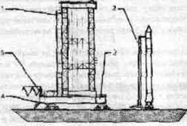
1 - elevator; 2 - cable mast; 3 - platform; 4 - movement mechanism; 5 - flexible pipeline; 6 - service tower
When rocket launches, it is connected to mating plates in the tail section of the launch vehicle, providing contact for more than five thousand electrical and pneumatic communications;
5) filling with toxic MCT is carried out in a closed cycle, excluding the exit or emission of MCT vapors into the PU premises and into the atmosphere. The oxidizer vapors are chemically neutralized, and the fuel vapors are burned.
RSC Zenit can carry out launches without direct human participation, that is, it was created in accordance with the concept of “unmanned launch” (Figures 6 and 7). Transportation of the ILV from the TC to the SC, the installation of the ILV on the PU, the docking of hydro, pneumatic and electrical communications is carried out in an automatic mode. In terms of the degree of automation and safety, RSC Zenit has no analogues in the world.
Get full textThe Launch LV is launched from a self-propelled launcher (Figure 9), mounted on the basis of a multi-axle wheeled chassis.
The design of the PU and the launch vehicle ensure long-term storage in readiness in a horizontal position. When the launch command is given, the transport and launch container with the ILV is transferred from the horizontal position to the vertical position in 40-50 s by means of a hydraulic power cylinder, then the powder pressure accumulator (PAD), located in the bottom of the TPK, provides a "mortar start", that is, PAD ejects the ILV at a speed of 70-80 km / h from TPK-At an altitude of 25-30 m from the Earth's surface, a sustainer engine is launched. Starting the main engine at a height almost completely eliminates the impact of the high-temperature jet of engine gases on the launcher, which significantly reduces the cost of post-launch repair and restoration work.

Figure 7 - Installation of the Zenit LV on the launcher:
1 - hydraulic supports TUA; 2 - arrow TUA; 3 - cable mast; 4 - hydraulic cylinders for lifting the boom TUA; 5 - branch pipes of the cooling system
Since the thrust-to-weight ratio of space rockets lies in the range of 1.4-1.8, they slowly leave the launcher, therefore, the high-temperature jet of propulsion gases affects the launcher for a long time. In order to reduce thermal, acoustic and mechanical loads on the gas duct and elements of the PU design, a water curtain is created in the flame zone. At SK RKK
For "Proton" and "Zenith", the docking mechanisms are protected by armored doors.
 |
1 - LV side board; 2 - cable-mast docking unit; 3 - cable mast; 4 - docking devices for communications for refueling SRT, helium and thermostating of the LV tail section; 5 - counterweight KM
Technological block designed to accommodate testing and starting equipment, a system for remote control of the LV refuelingcomponents of rocket propellants and compressed gases, as well as to accommodate the left calculation of the launch control panel.
Stationary storage facilities for KRT - structures in which tanks for storage of SRT are located, systems of supply and thermostating of SRT, fire extinguishing systems and other equipment.
A space rocket, 90-95% of the launch mass of which is made up of fire and explosive CMT, is an object of increased danger at the JV. Up to 20-25% of the entire mass of the MCT can participate in the formation of the explosion, the rest of the MCT is scattered by the blast wave onto
|
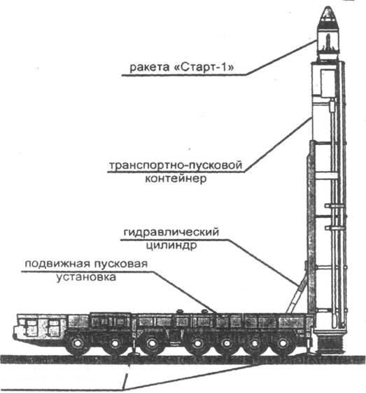
significant distances and forms a fire zone. Consequently, the explosion of a launch vehicle with a launch mass of 100 t is equivalent in power to an explosion of ~ 20 t TNT, and an explosion of a launch vehicle with an initial mass of 700 t is ~ 70 t TNT.
When launching ILV in the RSC position area, 3-4 safety zones are established, and depending on the nature and degree of risk in each zone, a strict regime of admission to work is ensured and appropriate safety measures are taken.
Characteristics of safety zones during launch of a super-heavy class Energia LV ":
1) an area with a radius of 2 km with a noise level of up to 13 5 dB; evacuation of personnel 2 hours before launch;
2) an area with a radius of 5 km with a noise level of less than 120 dB; evacuation 8 hours before launch;
3) an area with a radius of 8.5 km; evacuation 4 hours before launch;
4) an area with a radius of 15 km; evacuation 4 hours before launch.
Administrative and economic zone of RKK is intended for the placement and cultural and social services of the personnel of the launch unit, as well as for the placement of technical means intended to provide buildings and structures of the technical position with electricity, heat and water (Figure 10).
4 Characteristic of the loads acting on the lifted system of installers
4.1 Types of loads
Of all the operations performed when installing the rocket on the launch pad, the most laborious and time-consuming is the transfer of the rocket from the horizontal position to the vertical one, while at the same time on the boom lifting mechanism (Figure 1) from the side of the lifted system (SS), by which we mean the boom with the rocket or an arrow with a transport and installation trolley with a rocket, the moment of resistance created by
|
|||||||||||
| |
|||||||||||
| |
|||||||||||
Safety guard
Driveway
Figure 10 - Scheme of the administrative and economic zone of the RKK (in relation to the military unit)
weight, inertial and wind loads. The equation of moments for the rotational motion of the lifted system under the action of the lifting mechanism has the form
Get full text 
Or
MM = MG + MB + M in + MT, (1)
where MM - the moment developed by the lifting mechanism relative to the boom pivot axis; ...
Pg - hydraulic jack force;
a - hydraulic jack shoulder;
I - mass moment of inertia of the lifted system relative to the boom pivot axis;
Angular acceleration of the lifted system;
font-size: 14.0pt; line-height: 150% "> ј
R;
ј - linear acceleration of the center of gravity of the system;
R - radius of rotation of the center of gravity;
MG, M B, M in, MT - moments about the axis of rotation of the boom, respectively, from the forces of weight, the forces of inertia of the lifted system from the wind load acting on the system and from the forces of friction in the joints of the lifting mechanism.
To calculate the main parameters of the boom lifting mechanism, it is necessary to have the values of all moments as a function of the boom angle, i.e.
М G = f 1 (φ), MB = f 2 (φ), Мв = f 3 (φ), М T = f 4 (φ).
Let us consider sequentially the methods for determining these dependencies.
font-size: 14.0pt; line-height: 150%; color: black "> 4.2 Load moment
Moment from weight forces or load moment as a function of angle lifting is determined from expressions
MG = GRco s (
or MG = GXc ( co s (3) M G= f 1 () presentsis a cosine, therefore, it canbe built graphically without calculating it by points. Scheme graphic definitionM G and plotting the curve M G= f 1 ( YES B. From the vertical O D the angle is laid down and then the angle AOB equal to the boom lift angle 900.
Arc AB is divided into several equal parts (usually 6 or 9), and horizontal lines are drawn through the division points nii. On the axis in the accepted scale from the rocking coordinates fromthe corresponding points of division of the arc are put AB meaningangle font-size: 15.0pt; line-height: 150%; color: black; letter-spacing: -. 15pt "> Intersectioncorresponding horizons
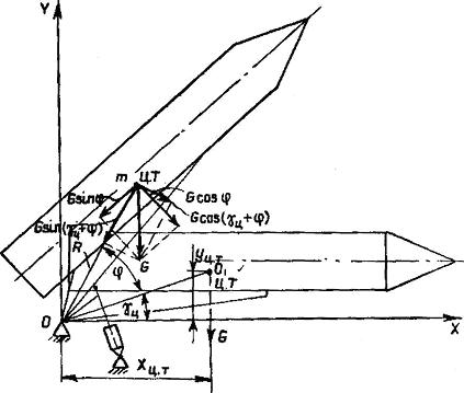
Figure 3 - Design scheme for determining the load moment
 |
The vertical and vertical lines give the points through which the curve passesMG= f 1 ( ).
Figure 4 - Graphical plotting of the load moment curve
MG changes its sign and from a moment that prevents the rise of the system, turns into a moment that facilitates its further movement. Under the influence of this moment, the system tends to overturn in the direction of the rise, and to prevent this, a resistance moment must be applied to the system being lifted, which balances the load moment, providing the main adjustment of the system to a vertical position.
5 Reporting of laboratory work
To defend the laboratory work, the student must submit a report made in accordance with ESKD. The volume of the report should be about 10 sheets of A4 format, it can be graphically executed by hand or on a printer.
The report should include:
Title page;
Introduction;
- content (calculated part of practical training);
Conclusion;
- bibliography.
Control questions
1 What is the purpose of the RKK?
2 What is included in the RKK structure?
3 What is the RKK classification?
4 What is the RKK position area?
5 What is the RKK technical position and what is its structure?
6 What is the structure of the assembly and test building?
7 What is the RKK's starting position and what is its composition?
8 What is the launch complex and what is its composition?
List of sources used
1 Cosmodrome / Under total. ed. ... - M .: Military Publishing, 1977.-
312 p .: ill.
Level measurement rollers. - M .: Mechanical Engineering, 1977.
3 Umansky-carriers. Cosmodromes. Ed.
M., Publishing house Restart +, 2001 .-- 216 p .: ill.
4 Operation of rocket and space complexes: Basic course of lectures
/ Under total. ed. ... - SPb .: VIKU im. ,
2001 .-- 496 p .: ill.
5 Carpin automation for measuring and dosing
Masses. - M .: Mechanical Engineering, 1971.
6, etc. Measurement of mass, volume and
Density. - M .: Publishing house. standards, 1972.