Circuits for testing varistors
The diagram in Fig. 1 allows you to remove volt-ampere I = f (U) and ampere-temperature characteristics of varistors I = f (θ)... Power supply voltage value E and load resistance R H are selected depending on the type of the investigated varistor.
When examining temperature dependences, the varistor is placed in a thermostat.
Thermistor (thermistor) Is a semiconductor resistor that uses the temperature dependence of the electrical resistance of a semiconductor.
In direct-fired thermistors, the resistance changes either due to heat or due to a change in the temperature of the thermistor due to a change in the thermal irradiation of the thermistor (for example, due to a change in temperature environment). The most widely used thermistors are thermistors, the main feature of which is a significant decrease in resistance with increasing temperature, that is, thermistors with a negative temperature coefficient of resistance.
A decrease in the resistance of a semiconductor with an increase in temperature can be due to various reasons - an increase in the concentration of charge carriers, an increase in their mobility, or phase transformations of a semiconductor material.
I. The first phenomenon is typical for thermistors made of single crystals of covalent semiconductors (silicon, germanium, silicon carbide, type A III B V compounds, etc.). Such semiconductors have a negative temperature coefficient of resistance in the temperature range corresponding to impurity electrical conductivity, when not all impurities are ionized, when the carrier concentration is due to ionization of the semiconductor's own atoms. In both cases, the dependence of the semiconductor resistance is determined mainly by the change in the concentration of charge carriers, since the temperature changes in the mobility are negligible in this case.
In these temperature ranges, the dependence of the semiconductor resistance on temperature corresponds to the equation
![]() , (6.1.1)
, (6.1.1)
where V- coefficient of temperature sensitivity; R¥ is a constant depending on the material and size of the thermistor.
With incomplete ionization and no compensation ![]() ,
,
where DE n- the ionization energy of impurities (donors or acceptors).
For a compensated semiconductor with incomplete ionization of impurities
![]() .
.
With its own electrical conductivity
![]() ,
,
where DE- the width of the forbidden zone of the semiconductor.
II. Most of the thermistors produced by the industry are made of polycrystalline oxide semiconductors - from oxides of the so-called transition metals from the periodic table (from titanium to zinc). Thermistors in the form of rods, tubes, discs or plates are produced by the method of ceramic technology, that is, by firing workpieces at a high temperature.
The electrical conductivity of oxide semiconductors with a predominant ionic bond between atoms differs from the electrical conductivity of covalent semiconductors. Transition metals are characterized by the presence of unfilled electron shells and variable valence. As a result, when an oxide is formed under certain conditions (presence of impurities, deviation from stoichiometry), ions with different charges appear in the same crystallographic positions. The electrical conductivity of such metals is associated with the exchange of electrons between neighboring ions. The energy required for such an exchange is small. Therefore, all electrons (or holes) that can pass from one ion to another can be considered free charge carriers, and their concentration is constant in the operating temperature range of the thermistor.
Due to the strong effect of charge carriers with ions, the mobility of charge carriers in an oxide semiconductor turns out to be small and experimentally increases with increasing temperature. As a result, the temperature dependence of the resistance of an oxide semiconductor thermistor is the same as that of a thermistor made of covalent semiconductors (Fig. 6.1.1), but the temperature sensitivity coefficient characterizes in this case a change in the mobility of charge carriers, and not a change in their concentration.
III. In vanadium oxides V 2 O 2 and V 2 O 3 at the temperature of phase transformations (68 o C and –110 o C), a decrease in resistivity by several orders of magnitude is observed. This phenomenon can also be used to create thermistors with a large negative temperature coefficient of resistance in the temperature range corresponding to phase transformation.
6.2. Characteristics and parameters of direct heating thermistors
Thermistor temperature characteristic Is the dependence of its resistance on temperature. An example of the temperature characteristic of one of the thermistors is shown in Fig. 6.2.1.
Thermistor nominal resistance- this is its resistance at a certain temperature (usually 20 ° C). Thermistors are manufactured with a permissible deviation from the nominal resistance of ± 20, 10 and 5%. The nominal resistances of various types of thermistors range from a few ohms to several hundred kilo-ohms.
![]() Temperature sensitivity coefficient B Is the coefficient in the exponent of the temperature characteristic of the thermistor (1). The value of this coefficient, depending on the properties of the thermistor material, is practically constant for a given thermistor in the operating temperature range and for various types of thermistors is in the range from 700 to 15 00 K. The temperature sensitivity coefficient can be found experimentally by measuring the resistance of the thermistor at two temperatures That and T according to the formula
Temperature sensitivity coefficient B Is the coefficient in the exponent of the temperature characteristic of the thermistor (1). The value of this coefficient, depending on the properties of the thermistor material, is practically constant for a given thermistor in the operating temperature range and for various types of thermistors is in the range from 700 to 15 00 K. The temperature sensitivity coefficient can be found experimentally by measuring the resistance of the thermistor at two temperatures That and T according to the formula
 . (6.2.1)
Thermistor temperature coefficient of resistance shows the relative change in resistance of the thermistor when the temperature changes by one degree:
TC  .(6.2.2)
The temperature coefficient of resistance is temperature dependent, so it must be written with an index indicating the temperature at which this value occurs. The dependence of the temperature coefficient on temperature can be obtained from equations (6.2.1) and (6.2.2):
TC R = - B / T 2 (6.2.3)
The value of the temperature coefficient of resistance at room temperature of various thermistors is in the range (0.8 - 6.0) × 10 -2 K -1.
Thermistor dissipation factor H numerically equal to the power dissipated by the thermistor when the temperature difference between the thermistor and the environment is one degree, or, in other words, it is numerically equal to the power that must be allocated in the thermistor from the current passing through it under conditions of thermal equilibrium between the thermistor and the environment
 Figure 6.2.2. shows the static current-voltage characteristics of thermistors. The linearity of the characteristics at low currents and voltages is explained by the fact that the power released in the thermistor is insufficient for a significant change in its temperature. With an increase in the current passing through the thermistor, the power released in it increases its temperature. The resistance of a thermistor is therefore determined by the combined ambient temperature and the temperature of the thermistor heater. At these currents, the resistance of the thermistor decreases with increasing current and temperature in accordance with (6.2.2), the linearity of the static current-voltage characteristic is violated. With a further increase in the current and a high temperature sensitivity of the thermistor, a falling section of the static current-voltage characteristic can be observed, that is, a decrease in the voltage across the thermistor with an increase in the current passing through it.
Maximum allowable thermistor temperature Is the temperature at which irreversible changes in the parameters and characteristics of the thermistor do not yet occur. The maximum allowable temperature is determined not only by the properties of the raw materials of the thermistor, but also by its design features.
Maximum allowable power dissipation of the thermistor- this is the power at which the thermistor, located in calm air at a temperature of 20 ° C, heats up when the current passes to the maximum allowable temperature. When the ambient temperature decreases, as well as when the thermistor operates in an environment that provides better heat dissipation, the power dissipation can exceed the maximum allowable value.
Thermistor energy sensitivity factor G numerically equal to the power that must be supplied to the thermistor to reduce its resistance by 1%. The energy sensitivity coefficient is related to the dissipation coefficient and the temperature coefficient of resistance by the relationship G = H / TK R.
The value of the coefficient of energy sensitivity depends on the operating mode of the thermistor, that is, it will be different at each point of the static current-voltage characteristic.
Thermistor time constant Is the time during which the temperature of the thermistor decreases by 63% (in e times) in relation to the temperature difference between the thermistor and the environment (for example, when the thermistor is transferred from an air environment with a temperature of 120 ° C to an air environment with a temperature of 20 ° C). Thermal inertia of a thermistor, characterized by its time constant, is determined by the design and dimensions of the thermistor and depends on the thermal conductivity of the medium to which the thermistor is located. For different types thermistors, the time constant is in the range from 0.5 to 140 s.
6.3. Indirect heating thermistors
An indirect heating thermistor is a thermistor that has an additional heat source - a heater.
The design of indirect heating thermistors can be different. Often, the heater is made in the form of a winding on an insulating tube, inside which a thermistor is located. In other cases, the thermistor is made in the form of a tube, inside which a heating thread passes. Common to all designs of indirect heating thermistors is that they have circuits electrically isolated from each other - control and controlled.
In addition to such parameters as the nominal resistance and the coefficient of temperature sensitivity, indirectly heated thermistors have their own specific characteristics and parameters.
Static current-voltage characteristics the indirect heating thermistor is removed at different currents through the heater. (Figure 6.3.1.).
Heating characteristic - this is the dependence of the resistance of the indirect heating thermistor on the power released in the heating coil (Fig. 6.3.2.).
To obtain the greatest sensitivity of the indirect heating thermistor, that is, the greatest change in resistance, it should be used in modes in which the power released in the thermosensitive element itself by the current passing through it could be neglected.
Thermal coupling coefficient Is the power ratio R T required to heat the temperature-sensitive element to a certain temperature during direct heating, to the power R under, required for heating to the same temperature with indirect heating, that is, by passing current through the heater:
K = P T / R under.
Typically, to determine the thermal coupling coefficient, an indirect heating thermistor is heated to the so-called hot resistance of the thermistor at the maximum power released in the heater. The thermal coupling coefficient is usually in the range from 0.5 to 0.97, that is, less than unity, since some of the heat generated by the heater is inevitably lost. Indirect heating thermistors are currently practically not used due to their large size, the need to use an additional power source for heating the thermistor, and high power consumption.
The circuit for studying direct heating thermistors, shown in Fig. 6.3.3, makes it possible to remove the current-voltage characteristics of thermistors at different ambient temperatures.
The voltage to the thermistor is supplied from a constant voltage source U power supply. Voltage is infinitely adjustable by potentiometer R in the power supply .
Good day! Today this article will have an easy way to check thermistor... Probably all radio amateurs know that there are two types of thermistors. NTC(Negative Temperature Coefficient) and PTC(Positive temperature coefficient). As their names suggest, resistance NTC thermistor will decrease with increasing temperature, and the resistance of the PTC thermistor with temperature rise - will increase... You can roughly check the NTC and PTC thermistors using any multimeter and soldering iron.
To do this, you need to switch the multimeter to the resistance measurement mode and connect its terminals to the terminals of the thermistor (polarity does not matter). Remember the resistance and bring the heated soldering iron to the thermistor and at the same time look at the resistance, it should increase or decrease. Depending on what type of thermistor you have in front of you is PTC or NTC. If everything is as described above - thermistor good.
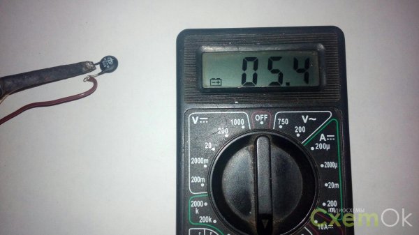
Now, how will it be in practice, but for practice I took the first thermistor I came across, it turned out to be an NTC thermistor MF72. First of all, I connected it to a multimeter, in order to film the verification process and due to the lack of crocodiles on the multimeter, I had to solder wires to the thermistor and then just screw them to the contacts of the multimeter.
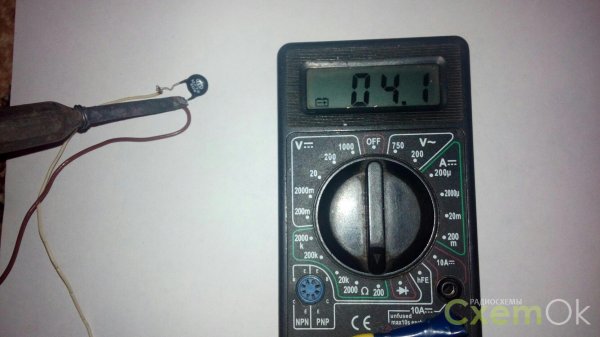
As you can see from the photo at room temperature, the resistance of the thermistor is 6.9 Ohm, this value is hardly correct, since the low battery indicator is on. Then I brought the soldering iron to the thermistor and touched the terminal a little to transfer heat from the soldering iron to the thermistor faster.
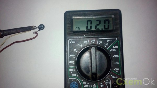
The resistance began to slowly decrease and stopped at a value of 2 Ohm, apparently at this temperature of the soldering iron this is the minimum value. Based on this, I am almost one hundred percent sure that this thermistor is working properly.
If the change in resistance is not smooth or not at all, any change means that the thermistor is not working properly.
Remember this is just a rough check... For an ideal test, you need to measure the temperature and the corresponding resistance of the thermistor, then compare these values with the datasheet for this thermistor.
Thermistors what are they
Thermistors and their applications
Thermistors are essentially resistance thermometers based on mixed oxides of transition metals. The two main types of thermistors are NTC (negative temperature coefficient of resistance) and PTC (positive coefficient). The most common type is NTC. PTC thermistors are used only in very narrow temperature ranges, several degrees, mainly in alarm and control systems.
The word "thermistor" is self-explanatory: THERMAL RESISTOR -
a device whose resistance changes with temperature.
Thermistors are largely non-linear devices and
often have parameters with a large scatter. That is why many, even
experienced engineers and circuit designers experience inconvenience when working with
with these devices. However, after getting to know these devices better, you can
see that thermistors are actually quite simple devices.
First, it must be said that not all devices that change
resistance with temperature are called thermistors. For example,
resistance thermometers, which are made from small coils of twisted
wire or from sprayed metal films. Although their parameters depend
on temperature, however, they work differently than thermistors. Usually the term
"Thermistor" applies to temperature sensitive
semiconductor devices.
There are two main classes of thermistors: NTC
(temperature coefficient of resistance) and with a positive TCR.
There are two fundamentally different types of thermistors available with
positive TCS. Some are manufactured like negative thermistors.
TCS, others are made of silicon. PTC thermistors will
are briefly described, with a focus on the more common
thermistors with negative TCS. Thus, if there are no special
instructions, we will talk about thermistors with negative TCS.
NTC thermistors are highly sensitive,
non-linear devices with a narrow range, the resistance of which
decreases with increasing temperature. Figure 1 shows the curve
showing the change in resistance depending on temperature and
which is a typical temperature dependence of resistance.
The sensitivity is approximately 4-5% / oC. Wide range available
resistance ratings, and the change in resistance can reach many
ohm and even kilo-ohms per degree.
Fig. 1 NTC thermistors are very sensitive and have significant
The degrees are non-linear. Ro can be in ohms, kilo-ohms or
megoomah:
1-resistance ratio R / Rо; 2- temperature in оС
Essentially thermistors are
semiconductor ceramics. They are made on the basis of oxide powders
metals (usually nickel and manganese oxides), sometimes with the addition of a small
the amount of other oxides. Powdered oxides are miscible with water and
various binders to obtain a liquid dough, which
given the required shape and which is fired at temperatures above
1000 oC.
A conductive metal coating (usually silver) is welded, and
leads are connected. The finished thermistor is usually epoxy coated
resin or glass, or enclosed in some other enclosure.
There are many types of thermistors.
Thermistors are in the form of discs and washers with a diameter of 2.5 to approximately 25.5
mm, the shape of rods of various sizes.
Some thermistors are first made as large plates,
and then cut into squares. Very small bead thermistors
are made by directly burning a drop of dough on two
conclusions from a refractory titanium alloy with subsequent lowering
thermistor in glass to obtain a coating.
Typical parameters
Saying "typical parameters" is not entirely correct, since for
thermistors, there are only a few typical parameters. For many
thermistors of various types, sizes, shapes, ratings and tolerances
there is an equally large number of specifications. Moreover,
often thermistors from different manufacturers are not
interchangeable.
Thermistors with resistances can be purchased (at 25 oС -
temperature at which the resistance of the thermistor is usually determined) from
one ohm to ten megohms or more. The resistance depends on the size and
the shape of the thermistor, however, for each specific type, the ratings are
resistances can differ by 5-6 orders of magnitude, which is achieved by
simple change of the oxide mixture. When changing the mixture, it also changes and
type of temperature dependence of resistance (R-T curve) and changes
stability at high temperatures... Fortunately, thermistors with high
resistance sufficient to use them at high
temperatures also tend to be more stable.
Inexpensive thermistors usually have fairly large tolerances
parameters. For example, allowable resistance values at 25 ° C
range from (20% to (5%. At higher or lower
at temperatures, the spread of parameters increases even more. For a typical
thermistor having a sensitivity of 4% per degree Celsius, corresponding
the measured temperature tolerances vary from approximately (5 o to (1.25
oC at 25 oC. High precision thermistors will be covered in this
article below.
It was previously said that thermistors are narrow
range. This needs to be clarified: most thermistors operate in
range from -80 ° C to 150 ° C, and there are instruments (usually with
glass coating), which operate at 400 ° C and high temperatures.
However, for practical purposes, the high sensitivity of thermistors
limits their useful temperature range. Typical resistance
thermistor can change 10,000 or 20,000 times at temperatures from -80
оС up to +150 оС. One can imagine the difficulties in designing a circuit,
which would ensure measurement accuracy at both ends of this range
(unless band switching is used). Thermistor resistance,
nominal at zero degrees, will not exceed a few ohms at
400 oC.
In most thermistors for internal terminal connection
soldering is used. Obviously, such a thermistor cannot be used for
measurements of temperatures exceeding the melting point of the solder. Even without
soldering, the epoxy coating of thermistors is retained only at a temperature not
more than 200 ° C. For higher temperatures it is necessary to use
glass coated thermistors having welded or fused
conclusions.
Stability requirements also limit the use of thermistors.
at high temperatures. The structure of thermistors begins to change when
exposure to high temperatures, and the rate and nature of change in
are largely determined by the oxide mixture and the manufacturing method
thermistor. Some drift of epoxy coated thermistors begins
at temperatures above 100 ° C or so. If such a thermistor
operates continuously at 150 ° C, the drift can be measured by several
degrees per year. Low resistance thermistors (for example, no more than 1000 ohms at 25
oC) is often even worse - their drift can be seen during operation
at approximately 70 ° C. And at 100 ° C they become unreliable.
Inexpensive devices with large tolerances are manufactured with less
attention to detail and can give even worse results. On the other side,
some properly designed glass-coated thermistors have
excellent stability even at higher temperatures. Bead
glass coated thermistors have very good stability,
as well as the recently introduced glass disc thermistors.
coated. It should be remembered that drift depends on both temperature and
time. For example, an epoxy thermistor can usually be used.
coating with short-term heating up to 150 ° C without significant drift.
When using thermistors, the nominal
constant power dissipation value. For example, a small thermistor with
epoxy coated has a dissipation constant of one milliwatt
per degree Celsius in still air. In other words, one milliwatt
power in the thermistor increases its internal temperature by one degree
Celsius, and two milliwatts (two degrees, and so on. If you submit
voltage of one volt per one kilo-ohm thermistor having a constant
dissipation of one milliwatt per degree Celsius, you get an error
measurements in one degree Celsius. Thermistors dissipate a lot of power,
if they sink into liquid. The same aforementioned small thermistor with
epoxy coating dissipates 8 mW / oC, being in good
stirring oil. Large thermistors have a constant
dispersion is better than small devices. For example, a thermistor in the form
disk or washer can dissipate power of 20 or 30 mW / oC in air
it should be remembered that in the same way as the resistance of a thermistor
varies with temperature, and its dissipated
power.
Thermistor Equations
There is no exact equation for describing the behavior of a thermistor, -
there are only approximate ones. Consider two commonly used
approximate equations.
The first approximate equation, exponential, is completely
satisfactory for limited temperature ranges, especially
- when using thermistors with low accuracy.
The second equation, called the Steinhart-Hart equation, provides
excellent accuracy for ranges up to 100 ° C.
NTC thermistor resistance decreases
approximately exponential with increasing temperature. In limited
temperature ranges, its R-T dependence is described quite well
by the following equation:
RT2 = RT1 e ((I / T2 - I / T1),
Where T1 and T2 are absolute temperatures in degrees Kelvin (оС +273);
RT1 and RT2 - resistances of the thermistor at T1 and T2; (- constant,
determined by measuring the resistance of the thermistor with two known
temperatures.
If (and RT1 are known, then this equation can be transformed and
use to calculate temperature by measuring resistance:
Beta is a large, positive number and has a dimension in
degrees Kelvin. Typical values range from 3000 to 5000 kK.
Manufacturers often include values for beta in their specs, however,
since the exponential equation is only approximate, the value
beta depends on the two temperatures used to calculate it.
Some manufacturers use 0 and 50 ° C values; others - 25 and 75 ° C.
Other temperatures can be used: can be calculated by yourself
beta value based on tables of resistance versus temperature,
offered by the manufacturer. The equation is generally consistent with
measured values within (1 ° C in a section of 100 ° C. Equation
cannot be used reliably at very different temperatures
from those that were used to determine the beta.
Before moving on to the Steinhart-Hart equation, consider two
other parameters often used to describe thermistors: alpha (() and
coefficient of resistance. Alpha is simply defined by the slope of the R-T curve,
that is, it is sensitivity at a certain temperature. Alpha
usually expressed as "percent per degree". Typical values range from 3
% up to 5% oC. Just like beta, alpha depends on the temperatures at which
it is determined. Its value will decrease slightly at higher
temperatures.
The drag coefficient means the ratio
resistance at one temperature to resistance at another, more
high temperature.
For precision thermistors, there is usually a table of resistance values.
(for each degree) depending on the temperature supplied
manufacturer together with other information. However, it is sometimes convenient to have
exact equation when performing design calculations or (especially) when
using a computer to convert the resistance of the thermistor to temperature.
Except for very narrow temperature ranges, the exponential equation
with one parameter is not satisfactory - a larger number is required
parameters.
The best approximate expression widely used today
time, is the Steinhart-Hart equation:
Where T- absolute temperature(in degrees Kelvin), R - resistance
thermistor; a, b and c are experimentally obtained constants.
Transformation of the equation in order to express the resistance in the form
function of temperature leads to a rather cumbersome expression.
However, it is easy to handle using a computer or programmable
calculator:
It should be noted that these values for alpha and beta are not
refer to the alpha and beta parameters used in exponential
equation with one parameter.
Although the Steinhart-Hart equation is more complex, it is usually
consistent with real values within a few thousandths of a degree in
ranges up to 1000 ° C. Of course it can be so good if
only the experimental values of the thermistor parameters are also accurate.
Temperatures with an accuracy of thousandths of a degree can only be obtained in
first-class laboratories. Rather, the user agrees to use
passport tables than he wants to take his own measurements.
To determine a, b and c, you need to know the exact resistance
thermistor at three temperatures and substitute each data set (R and T)
into the Steinhart-Hart equation to determine the three unknowns. Then
it is necessary to use mathematical means to simultaneously solve
three equations and obtaining the values of three constants. Using
passport tables, you need to choose the values of R depending on T at the edges and in
the middle of the temperature range to be used.
Manufacturers usually do not specify nameplate values for these constants, so
how these values change depending on the temperature used
range.
Precision thermistors
The parameters of ordinary thermistors are indicated only with deviations from + -
5% to + -20% at 25 ° C, and at other temperatures, the tolerances increase.
However, with appropriate control over technology and measurements, it is possible
get significantly higher accuracy. There are three types of precision
thermistors: precision interchangeable disc thermistors,
precision bead thermistors and matched bead pairs. Exact
thermistors provide electronic calibration of measuring instruments,
without requiring precise heating devices. Interchangeable thermistors also
allow you to replace the thermistor without recalibrating the electronics.
Precision interchangeable disc thermistors are manufactured with
careful control and change of R-T - parameters and stability of oxide
mixtures. Mixtures that do not meet stringent requirements do not
are used. Thermistors are mixed, shaped and fired using
conventional technologies. Then each thermistor is lowered into a liquid bath
at a carefully controlled temperature to adjust the resistance to
nominal value. Before shipment, the parameters of each thermistor
measured at two or three temperatures, and if they do not correspond
passport, the thermistor is rejected.
Ready-made, standardized thermistors with tolerances (0.2
oC or (0.1 oC in the range 0 -70 oC and less accuracy at -80 oC and +150
оС. There are special highly stable disc thermistors with glass
coating with tolerances not exceeding 0.05 ° C. High-precision data,
interchangeable thermistors are available in discs or squares only
small size, epoxy coated or (for higher
stability) glass. Several manufacturers offer some or all
from the following ratings (at 25 ° C): 100, 300, and 500 Ohm; 1.0,
2.252, 3.0, 5.0, 10.0, 30.0, 50.0, 100.0 and 300.0 kilo-ohms and 1 mega-ohm.
Thermistors with nominal values of 2.252; 3.0; and 5.0 kilo-ohms are interchangeable for
various manufacturers; other thermistors usually do not. There is
a large number of temperature sensors that use a thermistor
with a nominal value of 2.252 Kom.
Bead thermistors can be very accurate and stable, however
their small size and manufacturing methods make it impossible to fine-tune to
exact value. If the user needs to make accurate measurements
using bead thermistors (which have the smallest dimensions and
best performance at high temperatures), he may ask
change the manufacturer and print R-T values- curve for
each thermistor. Alternatively, you can specify thermistors selected from the range
ratings and having a certain tolerance at a certain temperature.
Another way that manufacturers ensure accuracy
and interchangeability, is the constant measurement of the parameters of each
thermistor and subsequent connection of selected matched pairs in parallel
or sequentially in order to provide a curve of a certain shape.
Temperature characteristics
Thermistors are resistors and they obey Ohm's Law (E = IxR) -
if their temperature does not change. It should be remembered that only
several milliwatts of power for that. To increase the temperature
thermistor by one degree or more, and that the resistance is reduced
approximately 4% per degree Celsius. If you connect to the thermistor
current source and slowly increase the current, it will be seen that the voltage
increases more and more slowly, as the resistance of the thermistor
decreases. Obviously, the voltage will stop increasing at all and
then it will practically begin to decrease with a further increase in the current. On
the graph in Fig. 4 shows typical volt-ampere curves. For small
current and low power, the curve corresponds to the line of constant resistance,
indicating that the thermistor is not hot enough. When increasing
power, you can see that the resistance of the thermistor begins to drop. In the area of
a large power thermistor in a sense, works like a negative
resistance, that is, the voltage across it decreases with increasing current.
Using thermistors
Thermistors are used in many areas. Almost none
a complex PCB is not complete without thermistors. They are used in
temperature sensors, thermometers, in almost any related
temperature conditions, electronics.
In fire-fighting technology, there are standard temperature
sensors. A similar sensor contains two negative thermistors.
temperature coefficient, which are installed on the printed circuit board in white
polycarbonate housing. One is brought out - an open thermistor, it
quickly responds to changes in air temperature. Another
thermistor is located in the housing and reacts to temperature changes
slower.
Under stable conditions, both thermistors are in thermal
equilibrium with air temperature and have some resistance. If
the air temperature rises rapidly, then the resistance of the open
thermistor becomes less than the resistance of the closed thermistor.
The resistance ratio of the thermistors is monitored by the electronic circuit, and if
this ratio exceeds the threshold level set at the factory, it
issues an alarm. In the future, this principle of action will be
referred to as “temperature rise rate response”. If the temperature
air rises slowly, the difference in the resistance of the thermistors
insignificantly. However, this difference becomes higher if you connect
high temperature resistor in series with a closed thermistor
stability. When the ratio of the sum of the resistances of the closed thermistor and
stable resistor and the resistance of the open thermistor exceeds
threshold, an alarm mode occurs. The sensor generates the "Alarm" mode when
reaching an external temperature of 60 ° C regardless of the rate of rise
temperature.
Thus, thermistors are ubiquitous in many
devices around us.
Bibliography
Shashkov A.G., Thermistors and their application. Moscow 1967.
Thermoelectric measuring transducers. Course Lecture
"Electrical measurements of mechanical quantities". Rostov-on-Don. 1977
Samy K. Measuring thermocouples and thermistors. Translation from the magazine
Otomesen 1988.Vol. 33. No. 5.
Share the link to the book with your friends:
Send a link to this book to a friend via ICQ or E-Mail:Post on your resource or LJ:
Learn about thermistors and how to program the Arduino to measure their data.
Have you ever wondered how some devices such as thermostats, 3D printer heating pads, car engines and ovens measure temperature? You can find out in this article!
Knowing the temperature can be very helpful. Knowing the temperature can help adjust the room temperature to a comfortable temperature, ensure that the 3D printer's heating pad is hot enough for materials such as ABS to stick to its surface, and prevent the engine from overheating or burning food being cooked.
In this article, we are considering only one type of sensor capable of measuring temperature. This sensor is called a thermistor.
A thermistor has a resistance that is much more dependent on temperature than other types of resistors.
We will be using the Arduino to measure and process the thermistor readings, and then we convert those readings into an easy to read temperature unit format.
Below is a photo of the thermistor we are going to use:
Required components
Components
- Arduino (Mega or Uno or any other model);
- several jumpers;
- soldering iron and solder (may be needed if your thermistor won't fit into the connectors on the Arduino board).
Software
- Arduino IDE
Theory
With typical resistor use, you do not want its resistance to change as the temperature changes. This is not realistic in real life, you can only provide a small change in resistance with a large change in temperature. If this were not the case, then the resistors would strangely affect the operation of the circuits, for example, the LED could glow much brighter or dimmer as the ambient temperature changes.
But what if you really want the brightness of an LED to be a function of temperature? This is where the thermistor comes in. As you might have guessed, the resistance of a thermistor changes dramatically with a small change in temperature. To illustrate this, the following is a thermistor resistance curve:
The figure shows only units of measurement without actual values, since the resistance range depends on the type of specific thermistor. As you can see, as the temperature rises, the resistance of the thermistor decreases. This is the hallmark of the Negative Temperature Coefficient resistor, or NTC thermistor for short.
There are also Positive Temperature Coefficient (PTC) thermistors whose resistance increases as the temperature rises. However, PTC thermistors have a kind of inflection point and change resistance a lot at a certain temperature. This makes interfacing with PTC thermistors a little more difficult. For this reason, NTC thermistors are preferred in most cheap temperature meters.
For the rest of this article, as you might guess, we will be talking about NTC type thermistors.
Four Approaches to Finding a Curve Formula
Now that we understand better the behavior of thermistors, you may wonder how we can use the Arduino to measure temperature. The curve in the graph above is non-linear and therefore a simple linear equation does not work for us (in fact, we can derive the equation, but more on that later).
So what do you do?
Before proceeding, think about how you would do it on an Arduino, or even in a circuit without microprocessor components.
There are several ways to solve this problem, which are listed below. This is far from full list of all techniques, but he will show you some popular approaches.
Method 1
Some manufacturers provide information so complete that it contains an entire graph displaying specific ranges of integer temperature and resistance values (typical values). One such thermistor can be found in the Vishay datasheet.
How, with such detailed data, it would be possible to implement temperature measurement on an Arduino. You would need to hard code all of these values into a huge lookup table or very long "switch ... case" or "if ... else" control structures.
And if the manufacturer did not bother to provide a detailed table, then you will have to measure each point yourself to form such a table. This day will be pretty dull for a programmer. But this method is not so bad and has a place to be used. If the current project is checking only a few points or even a small range, this method may be preferable. For example, one such situation arises if you want to measure if the values are in selected temperature ranges and light up an LED to indicate this condition.
But in our project, we want to measure temperature in an almost continuous range and send the reading to the serial port monitor, so we will not use this method.
Method 2
You can try to "linearize" the response of the thermistor by adding additional circuitry to it.
One popular way of doing this is by connecting a resistor in parallel with the thermistor. Some chips offer to do this for you.
Determining how to select and linearize a portion of the curve, along with choosing the correct resistor value, is a topic for a separate article. This approach is good if the microprocessor cannot compute floating point expressions (such as PICAXE), as it simplifies the response over a certain temperature range to linearity. It also makes it easier to design a circuit that does not have a microprocessor.
But we have a microprocessor in this article, and we want to measure the temperature over the entire range.
Method 3
You can take data from table in technical description or (if you like perversions) create your own table by taking independent measurements and recreating the graph in something like Excel. Then you can use the curve fitting function to create a formula for that curve. This is not a bad idea, and all the work done will give you a nice formula that you can use in your program. But it will take some time for data preprocessing.
While this is a sensible approach, we do not want to depend on analyzing all of this data. Also, each thermistor is slightly different (but of course this is not a problem if the tolerance is rather low).
Method 4
It turns out there is a general curve fitting formula for devices like thermistors. It is called the Steinhart-Hart equation. Below is a version of it (in other versions, terms in the second and degree are used):
\ [\ frac (1) (T) = A + B \ ln (R) + C (\ ln (R)) ^ 3 \]
where R is the resistance of the thermistor at temperature T (in Kelvin).
This is a general curve equation suitable for all types of NTC thermistors. The approximation of the relationship between temperature and resistance is “good enough” for most applications.
Note that the equation needs constants A, B and C. These are different for different thermistors and must either be specified or calculated. Since we have three unknowns, you need to make three measurements of resistance at specific temperatures, which can then be used to create three equations and determine the values of these constants.
Even for those of us who know algebra well, it is still too time consuming.
Instead, there is an even simpler equation that is less accurate, but contains only one constant. This constant is denoted as β, and therefore the equation is called β-equation.
\ [\ frac (1) (T) = \ frac (1) (T_o) + (\ frac (1) (\ beta)) \ cdot \ ln \ left (\ frac (R) (R_o) \ right) \ ]
where R 0 - resistance at the control temperature T 0 (for example, resistance at room temperature). β is usually indicated in the datasheet; if not, then you only need one dimension (one equation) to calculate this constant. I will use this equation to interact with our thermistor, since it is the simplest one I have encountered and does not need to linearize the thermistor response.
Measuring resistance with Arduino
Now that we have chosen the curve fitting method, we need to figure out how to actually measure resistance with the Arduino before we can feed the resistance information into the β-equation. We can do this using a voltage divider:
This will be our thermistor interaction circuit. When the thermistor senses a change in temperature, this will be reflected in the output voltage.
Now, as usual, we use the voltage divider formula.
But we are not interested in the output voltage V output, we are interested in the resistance of the thermistor R thermistor. Therefore, we will express it:
This is much better, but we need to measure our output voltage as well as the supply voltage. Since we are using the Arduino's built-in ADC, we can represent the voltage as a numerical value on a specific scale. So, the final form of our equation is shown below:
This works because no matter how we represent voltage (in volts or in digital units), these units cancel out in the numerator and denominator of the fraction, leaving a dimensionless value. Then we multiply it by the resistance to get the ohm result.
We will have D max equal to 1023, since this is the largest number that our 10-bit ADC can produce. D measured is the measured value of the analog-to-digital converter, which can range from zero to 1023.
Everything! Now you can start assembling!
Let's put it together
I used a TH10K thermistor.
I also used a 10k resistor as the R balance in our voltage divider. I didn't have the constant β, so I calculated it myself.
Below is a complete diagram of the device. It's pretty straightforward.
And this is how the final layout looks like:
Arduino code
The code has a lot of comments to help you understand the logic of the program.
It basically measures the voltage across the divider, calculates the temperature, and then displays it in the serial port terminal.
For fun, some "if ... else" statements have also been added to show how you can act depending on the temperature range.
// ================================================ =============================== // Constants // =============== ================================================== =============== // Thermistor related: / * Here we have some constants that make it easier to edit the code. Let's walk through them. A read from the ADC can give one value on one sample, and then a slightly different value on the next sample. To avoid the influence of noise, we can read the values from the ADC pin several times and then average the values to get a more constant value. This constant is used in the readThermistor function. * / const int SAMPLE_NUMBER = 10; / * To use the beta equation, we need to know the value of the second resistor in our divider. If you are using a resistor with a large tolerance like 5% or even 1%, measure it and put the ohm reading here. * / const double BALANCE_RESISTOR = 9710.0; // This helps in calculating the resistance of the thermistor (see article for details). const double MAX_ADC = 1023.0; / * This constant is thermistor dependent and should be in the datasheet, or see the article on how to calculate it using the beta equation. * / const double BETA = 3974.0; / * Required for the conversion equation as "typical" room temperature. * / const double ROOM_TEMP = 298.15; // room temperature in Kelvin / * Thermistors have a typical resistance at room temperature, we indicate it here. Again, needed for the transformation equation. * / const double RESISTOR_ROOM_TEMP = 10000.0; // ================================================ =============================== // Variables // ============== ================================================== =============== // Here we will store the current temperature double currentTemperature = 0; // ================================================ =============================== // Declaration of conclusions // ============== ================================================== ================ // Inputs: int thermistorPin = 0; // ADC input, voltage divider output // ======================================= ======================================= // Initialization // ====== ================================================== ======================= void setup () (// Set port speed for sending messages Serial.begin (9600);) // ==== ================================================== ========================== // Main loop // ==================== ================================================== ========== void loop () (/ * The main loop is pretty simple, it prints the temperature to the serial monitor. The heart of the program is in the readThermistor function. * / currentTemperature = readThermistor (); delay (3000); / * Here's what to do if the temperature is too high, too low, or perfect. * / if (currentTemperature> 21.0 && currentTemperature< 24.0) { Serial.print("It is "); Serial.print(currentTemperature); Serial.println("C. Ahhh, very nice temperature."); } else if (currentTemperature >= 24.0) (Serial.print ("It is"); Serial.print (currentTemperature); Serial.println ("C. I feel like a hot tamale!");) Else (Serial.print ("It is") ; Serial.print (currentTemperature); Serial.println ("C. Brrrrrr, it" s COLD! ");)) // ===================== ================================================== ======== // Functions // ===================================== ========================================== //////// ///////////////////// ////// readThermistor /////// /////////////// ////////////// / * This function reads the values from the analog output as shown below. Converts the input voltage to digital representation using an analog-to-digital conversion. However, this is done several times so that we could have averaged the value to avoid measurement errors. This averaged value is then used to calculate the resistance of the thermistor. The resistance is then used to calculate the temperature of the thermistor. Finally, the temperature is converted to degrees Celsius. * / double readThermistor () (// variables double rThermistor = 0; // Stores the resistance value of the thermistor double tKelvin = 0; // Stores the calculated temperature double tCelsius = 0; // Stores the temperature in degrees Celsius double adcAverage = 0; // Stores the average voltage value int adcSamples; // Array for storing individual results // of voltage measurements / * Calculate the average resistance of the thermistor: As mentioned above, we will read the ADC values several times to get an array of samples. A small delay is used for the analogRead function to work correctly. * / for (int i = 0; i< SAMPLE_NUMBER; i++) { adcSamples[i] = analogRead(thermistorPin); // прочитать значение на выводе и сохранить delay(10); // ждем 10 миллисекунд } /* Затем мы просто усредняем все эти выборки для "сглаживания" измерений. */ for (int i = 0; i < SAMPLE_NUMBER; i++) { adcAverage += adcSamples[i]; // складываем все выборки. . . } adcAverage /= SAMPLE_NUMBER; // . . . усредняем их с помощью деления /* Здесь мы рассчитываем сопротивление термистора, используя уравнение, описываемое в статье. */ rThermistor = BALANCE_RESISTOR * ((MAX_ADC / adcAverage) - 1); /* Здесь используется бета-уравнение, но оно отличается от того, что описывалось в статье. Не беспокойтесь! Оно было перестроено, чтобы получить более "красивую" формулу. Попробуйте сами упростить уравнение, чтобы поупражняться в алгебре. Или просто используйте показанное здесь или то, что приведено в статье. В любом случае всё будет работать! */ tKelvin = (BETA * ROOM_TEMP) / (BETA + (ROOM_TEMP * log(rThermistor / RESISTOR_ROOM_TEMP))); /* Я буду использовать градусы Цельсия для отображения температуры. Я сделал это, чтобы увидеть типовую комнатную температуру, которая составляет 25 градусов Цельсия. */ tCelsius = tKelvin - 273.15; // преобразовать кельвины в цельсии return tCelsius; // вернуть температуру в градусах Цельсия }Possible next steps
Everything in this article shows a fairly simple way to measure temperature using a cheap thermistor. There are a couple more ways to improve the circuit:
- add a small capacitor parallel to the divider output. This stabilizes the voltage and may even eliminate the need to average a large number of samples (as was done in the code) - or at least we can average fewer samples;
- use precision resistors (less than 1% tolerance) for more predictable measurements. If you are critical of measurement accuracy, keep in mind that self-heating of the thermistor can affect the measurement; self-heating is not compensated for in this article.
Of course, thermistors are just one of the sensors used to measure temperature. Another popular choice is sensor chips (an example of working with one of them is described). In this case, you do not have to deal with linearization and complex equations. The other two options are thermocouple and infrared sensor type; the latter can measure temperature without physical contact, but is not so cheap anymore.
Hope the article was helpful. Leave your comments!